15
ASSEMBLY PROCEDURE 2D MOTORIZED SYSTEM
(BEFORE NOVEMBER 2023)
1 ⸀ Follow step 1 and 2 from the 1D assembly procedure ⸀
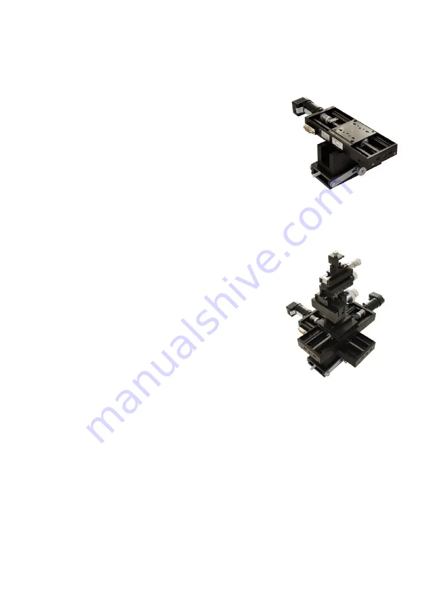
2 ⸀ Mount one motor stage
across
the U-pro昀椀le (see picture). Move the
stage plate completely down by turning the spindle joint with a 昀椀nger
and mount two of the provided large screws in the two upper of the
four central holes in the back of the stage as shown below ⸀ Then
turn the spindle to move the stage plate completely in the opposite
direction and mount two of the provided large screws in the bottom
holes ⸀
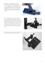
3 ⸀
Place the second motor stage on the 昀椀rst one. The second stage must
be perpendicular to the 昀椀rst one. Orient the second stage so that
the motor points in the direction where the tilting plate is hinged (see
step 3 in the 1D assembly procedure above) ⸀ Move the stage plate
completely down by turning the spindle joint with a 昀椀nger and mount
two of the provided screws in the two upper of the four central holes in
the back of the stage ⸀ Then turn the spindle to move the stage plate
completely in the opposite direction to mount two of the provided
screws in the bottom holes ⸀
4 ⸀ The provided square plate has four holes: two center holes near the
middle and two corner holes near the corners ⸀ With the 1D MMS neck
(controller connection) pointing
upwards
, mount the plate with the
two center holes located just right of the middle ⸀ Use the large screws
(see picture under 1D motor mounting)
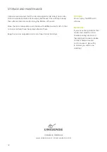
5 ⸀ Mount the MM33 or MM33-2 on the plate using the two screws from
step 1 in the 1D assembly procedure ⸀


