output
November 19, 2019
13:11
Page 11
SulfiLogger_Manual_EN_203.pdf
M
EC
H
A
N
IC
A
L
IN
ST
A
LL
A
T
IO
N
The
Sul
fiL
ogger
™
sensor
can
be
installed
in
four
different
wa
ys:
a)
Free
hanging
(liquids)
b)
Fix
ed
(liquids)
c)
Inline
(gases)
d)
Fix
ed
(gases)
FL
OW
a)
b)
c)
d)
x
x
a)
Free
hanging
(liquids)
This
mounting
option
is
ideal
for
low
flow
reserv
oirs
and
channels
and
gener
ally
suit-
able
for
short
measurement
campaigns.
The
Sul
fiL
ogger
™
sensor
is
installed
at
the
end
of
an
extension
pipe,
attached
to
an
an-
chor
point
using
a
steel
wire
and
suspended
down
into
the
sewage.
The
extension
pipe
ensures
that
the
cables
and
connectors
are
protected
from
fouling.
To
perform
this
installation,
you
must
ensure:
•
That
the
circulation
in
the
reserv
oir
is
suf-
ficient
to
ensure
good
mixing.
•
That
the
sensor
tip
can
not
touch
the
walls
and
bottom
of
the
reserv
oir
,espe-
cially
during
high
flows.
If
there
is
a
risk
of
the
sensor
hitting
the
walls,
then
you
should
perform
the
"fi
xed
(liquids)"
instal-
lation
instead.
•
That
you
ha
ve
a
suitable
anchor
point
available
to
attach
the
steel
wire
to.
•
That
the
length
of
the
steel
wire
allows
the
sens
or
to
remain
in
the
liquid
at
all
times
while
the
back
of
the
extension
pipe
at
the
same
time
remains
out
of
the
liquid.
b)
Fix
ed
(liquids)
This
mounting
option
is
ideal
for
permanent
installations
in
low
and
high
flow
reserv
oirs
and
channels.
It
is
similar
to
the
"F
ree
hang-
ing
(liquids)"
installation
in
most
regards
but
here,
the
extension
pipe
(and
sensor)
is
fixated
-
not
hanging
in
the
steel
wire.
Unisense
does
not
supply
br
ack
ets
or
an
y
other
materials
for
this
installation
method.
c)
Inline
(gases)
Directly
on
the
main
pipe
The
Sul
fiL
ogger
™
sensor
can
be
installed
on
a
pipe
stub
allowing
measurement
in
a
closed
system.
•
Before
installing
the
pipe
stub
a
30
mm
hole
must
be
drilled
in
the
main
pipe.
•
The
pipe
stub
is
supplied
by
Unisense
and
must
be
welded
onto
the
main
pipe.
•
Use
a
spanner
(size
36)
to
screw
the
Sul-
fiL
ogger™
sensor
onto
the
pipe
stub.
•
Beware
of
the
pressure
rating
of
the
Sul-
fiL
ogger
™
sensor
and
ensure
that
the
pressure
pipe
system
does
not
ex
ceed
the
pressure
limit.
Bypass
flow
using
a
flow
cell
A
portion
of
the
flow
can
be
di-
rected/b
ypassed
into
a
flow
cell
on
which
the
Sul
fiL
ogger™
sensor
is
installed.
•
Before
the
installation,
please
ensure
that
the
pressure
and
temper
ature
rat-
ings
of
the
bypassed
flow
are
within
the
speci
fications
of
the
Sul
fiL
ogger
™
sensor
.
•
The
flow
cell
is
supplied
by
Unisense.
•
Use
a
spanner
(size
36)
to
screw
the
Sul-
fiL
ogger™
sensor
onto
the
flow
cell.
d)
Fix
ed
(gases)
The
Sul
fiL
ogger
™
sensor
can
be
mounted
in
pump
wells,
reserv
oirs
etc.
abo
ve
wa-
ter
le
vel
for
gas
phase
measurements.
The
outer
diameter
of
the
Sul
fiL
ogger
™
sen-
sor
resembles
a
1.5
"pipe
and
can
thus
be
mounted
using
a
standard
1.5
"pipe
ring.
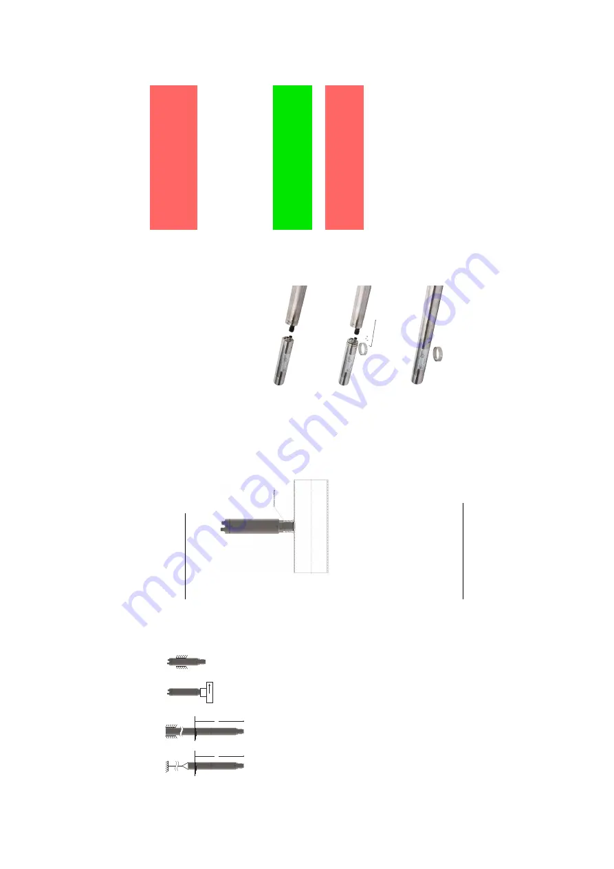
Extension
pipe
installation
For
free
hanging
and
fix
ed
measurements
in
liquids,
an
extension
pipe
must
be
at-
tached
to
the
Sul
fiL
ogger
™
sensor
.This
fig-
ure
shows
the
steps
needed
to
perform
this
installation:
•
Unscrew
the
three
he
x
screws
on
the
back
of
the
Sul
fiL
ogger
™
sensor
and
re-
mo
ve
the
outer
ring.
•
Feed
the
cables
through
the
extension
pipe
and
attach
them
to
the
connectors
on
the
sensor
.
•
Align
the
sensor
with
the
screw
holes
of
the
extension
pipe
and
screw
in
the
three
he
x
screws
to
secure
the
sensor
to
the
extension
pipe.
Temper
ature
rating
The
sensor
is
designed
to
withstand
temper-
atures
from
-20
◦
C
to
+60
◦
C.
D
ANGER
Exposing
a
Sul
fiL
ogger
™
sensor
from
the
X1-series
for
ambient
temper
a-
tures
lower
than
-20
◦
C
or
higher
than
+60
◦
C
will
void
the
ATEX
certi
ficate.
The
sensor
,both
S1
and
X1
series,
performs
optimally
between
0
◦
C
and
+40
◦
C.
Disassembly
W
e
do
not
recommend
you
to
disassemble
the
Sul
fiL
ogger™sensor.
IMPOR
TANT
NO
TE
Disassembly
of
the
sensor
will
void
the
warr
anty
and
render
the
sensor
non-
functional.
D
ANGER
Disassembly
of
a
Sul
fiL
ogger
™
sensor
from
the
X1-series
will
void
the
ATEX
certi
ficate.
S
U
P
P
O
R
T
Unisense
A/S
Tueager
1
DK
-8200
Aarhus
N
Denmark
E-mail:
Sul
fiL
ogger@unisense.com
Tel:
+45
8944
9500
Fax:
+45
8944
9549
For
further
documentation,
the
latest
User
Manual
and
other
resources,
please
visit
the
Sul
fiL
ogger™
sensor
website:
www
.Sul
fiL
ogger
.com
11


