Digital Network Video Surveillance System
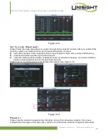
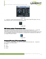
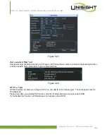
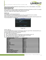
Figure 4-42
Activate Pattern Function
In
X346H346H346H316H316H316H323H
Figure 4-35, input mode value in the No. blank, and click pattern button.
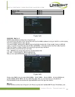
Auto Scan Setup
In
X347H347H347H317H317H317H324H
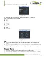
Figure 4-34, click border button. The interface is shown as in
X348H348H348H318H318H318H325H
Figure 4-39.
Please go to
X349H349H349H319H319H319H326H
Figure 4-31
X
, use direction arrows to select camera left limit
Then please go to
X350H350H350H320H320H320H327H
Figure 4-39
X
and click left limit button
Repeat the above procedures to set right limit.
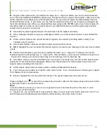
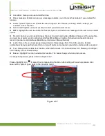
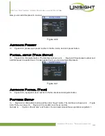
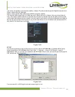
Figure 4-43
Activate Auto Scan
In
X351H351H351H321H321H321H328H
Figure 4-35
X
, click “Auto Scan” button, the system begins auto scan. Correspondingly, the auto scan
button becomes Stop button. Click stop button to terminate scan operation.
Flip
In
X352H352H352H322H322H322H329H
Figure 4-35
X
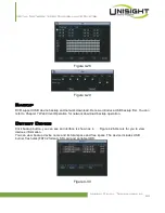
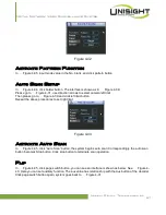
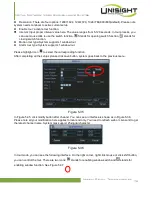
, click page switch button, you can see an interface is shown as below. See
X353H353H353H323H323H323H330H
Figure 4-
40
X
. Here you can set auxiliary function. The aux value has relation ship with the Aux button of the decoder.
Click page switch button again, system goes back to
X354H354H354H324H324H324H331H
Figure 4-31.
Unisight Digital Technologies, Inc.
57

