Digital Network Video Surveillance System
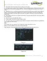
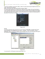
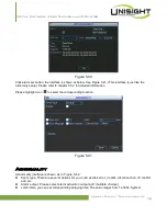
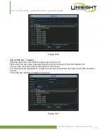
Figure 5-40
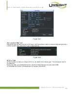
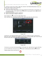
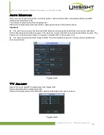
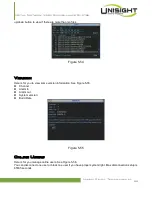
Click alarm set button, the interface is shown as below. See Figure 5-41. (This interface is just like the
abnormity setup). Please refer to chapter 5.5.2 for detailed information.
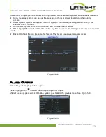
Please highlight icon
to select the corresponding function.
Figure 5-41
Abnormality
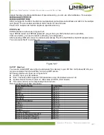
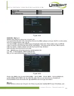
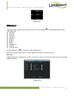
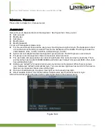
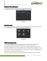
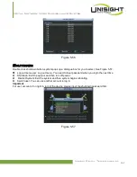
Abnormality interface is shown as in Figure 5-42.
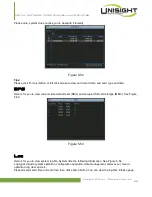
Event type: There are several options for you such as disk error, no disk, disconnection, IP conflict
and etc.
Alarm output: Please select alarm activation output port (multiple choices).
Latch: Here you can set corresponding delaying time. The value ranges from 1s-300s. System
Unisight Digital Technologies, Inc.
75

