26
Unison
®
ERn Rack Mount Enclosure Installation Manual
Aux Power and LinkPower Status Indicators
When power is applied to the ERn, the Paradigm repeater module LEDs located on the front panel
illuminate, indicating the status of the auxiliary power, LinkConnect control network, and connected
stations.
The Aux Power and LinkPower LEDs indicate in green when the Paradigm station power module is
connected properly and auxiliary power and LinkPower are present. When there is an unbalance in
LinkPower the fault indicators illuminate. This condition typically means that the station wiring is at
fault, however it could mean a connected device is having an issue. A qualified technician should
inspect the system wire and terminations first, then proceed to disconnecting devices to pinpoint the
fault and correct it. The power supply will update the fault indicators automatically when the fault
condition is cleared.
• If the NET A line has a fault (is shorted or has leakage to ground), the Fault + LED lights.
• If the NET B line has a fault (is shorted or has leakage to ground), the Fault - LED lights.
• If neither fault LED is illuminated the data connections are properly installed and the stations are
receiving the data and power required for operation.
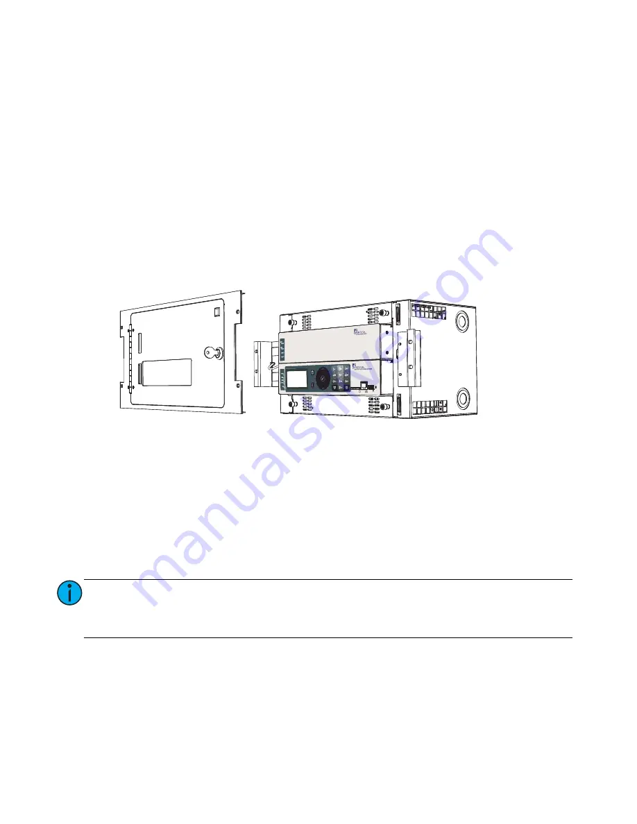
Final Installation
1: Install the Paradigm architectural control processor (P-ACP) in the appropriate module slot.
2: Install the Paradigm station power module (P-SPM) in the module slot above the Paradigm
architectural control processor.
3: Install option modules if they are not installed. For an ERn4, you may install a Paradigm dual
repeater module (P-DREP), two blank modules, or a Paradigm station repeater module (P-REP) in
the top module slot of the enclosure with a blank module below.
4: Install either the ERn blank option module or the redundant power supply (ERn-RPS) in the lower
option module slot.
a: If installing the redundant rack power supply (ERn-RPS) module in the option module slot, be
certain you have completed the installation requirements. See
Install Rack Options
on
page 19
.
5: Install blank air flow (ERn-BM) modules in any unused module slot in the enclosure to maintain
the required convection cooling requirements.
6: For 230 VAC CE ERn enclosures, reinstall the module retention bar to the left side of the ERn
enclosure. This module retention bar is required to maintain CE compliance.
Note:
The optional redundant power supply (ERn-RPS) is not supported in ERn4 enclosures
at 230 VAC. Instead the ERn4 at 230 VAC is shipped from the factory with a rack
power supply installed in the top (normal) position and in the lower option module
slot as standard.


