290982-UIM-C-0907
R-22
OUTDOOR SPLIT-SYSTEM
AIR CONDITIONING
MODELS: 13 SEER
TCGD12 - 60 & GCGD12 - 60 SERIES
1 TO 5 TONS
INSTALLATION MANUAL
LISTED
ISO 9001
Certified Quality
Management System
SECTION I: GENERAL
The outdoor units are designed to be connected to a matching indoor
coil with sweat connect lines. Sweat connect units are factory charged
with refrigerant for a matching indoor coil plus 15 feet of field supplied
lines.
The refrigerant charge may need to be changed for some indoor-out-
door unit combinations, elevation differences or total line lengths. Refer
to Application Data covering “General Piping Recommendations and
Refrigerant Line Length” (Part Number 247077).
SECTION II: SAFETY
This is a safety alert symbol. When you see this symbol on
labels or in manuals, be alert to the potential for personal
injury.
Understand and pay particular attention to the signal words
DANGER
,
WARNING
, or
CAUTION
.
DANGER
indicates an
imminently
hazardous situation, which, if not
avoided,
will result in death or serious injury
.
WARNING
indicates a
potentially
hazardous situation, which, if not
avoided,
could result in death or serious injury
.
CAUTION
indicates a potentially hazardous situation, which, if not
avoided
may result in minor or moderate injury
. It is also used to
alert against unsafe practices and hazards involving only property dam-
age.
INSPECTION
As soon as a unit is received, it should be inspected for possible dam-
age during transit. If damage is evident, the extent of the damage
should be noted on the carrier’s delivery receipt. A separate request for
inspection by the carrier’s agent should be made in writing. See Local
Distributor for more information.
LIMITATIONS
The unit should be installed in accordance with all National, State and
Local Safety Codes and the limitations listed below:
1.
Limitations for the indoor unit, coil, and appropriate accessories
must also be observed.
2.
The outdoor unit must not be installed with any duct work in the air
stream. The outdoor fan is the propeller type and is not designed
to operate against any additional external static pressure.
3.
The maximum and minimum conditions for operation must be
observed to ensure a system that will give maximum performance
with minimum service.
4.
The unit should not be operated at outdoor temperatures below
50° F without an approved low ambient operation accessory kit
installed.
Improper installation may create a condition where the operation of
the product could cause personal injury or property damage.
Improper installation, adjustment, alteration, service or mainte-
nance can cause injury or property damage. Refer to this manual
for assistance or for additional information, consult a qualified con-
tractor, installer or service agency.
This product must be installed in strict compliance with the
enclosed installation instructions and any applicable local, state,
and national codes including, but not limited to building, electrical,
and mechanical codes.
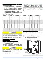
TABLE 1:
Application Limitations
Ambient Air Temperature
on Outdoor Coil
Air Temperature on
Indoor Coil
Min. DB
Max. DB
Min. WB
Max. WB
50 °F
115 °F
57 °F
72 °F
LIST OF SECTIONS
GENERAL . . . . . . . . . . . . . . . . . . . . . . . . . . . . . . . . . . . . . . . . . . . . . . 1
SAFETY . . . . . . . . . . . . . . . . . . . . . . . . . . . . . . . . . . . . . . . . . . . . . . . . 1
UNIT INSTALLATION . . . . . . . . . . . . . . . . . . . . . . . . . . . . . . . . . . . . . 2
ORIFICE INSTALLATION . . . . . . . . . . . . . . . . . . . . . . . . . . . . . . . . . . 4
TXV INSTALLATIONS . . . . . . . . . . . . . . . . . . . . . . . . . . . . . . . . . . . . .5
EVACUATION . . . . . . . . . . . . . . . . . . . . . . . . . . . . . . . . . . . . . . . . . . .5
SYSTEM CHARGE . . . . . . . . . . . . . . . . . . . . . . . . . . . . . . . . . . . . . . .5
ELECTRICAL CONNECTIONS . . . . . . . . . . . . . . . . . . . . . . . . . . . . . .6
INSTRUCTING THE OWNER . . . . . . . . . . . . . . . . . . . . . . . . . . . . . .12
LIST OF FIGURES
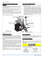
Typical Installation . . . . . . . . . . . . . . . . . . . . . . . . . . . . . . . . . . . . . . . . 2
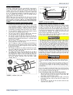
Installation of Vapor Line . . . . . . . . . . . . . . . . . . . . . . . . . . . . . . . . . . . 3
Underground Installation . . . . . . . . . . . . . . . . . . . . . . . . . . . . . . . . . . . 3
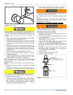
Heat Protection . . . . . . . . . . . . . . . . . . . . . . . . . . . . . . . . . . . . . . . . . . 4
Orifice Installation . . . . . . . . . . . . . . . . . . . . . . . . . . . . . . . . . . . . . . . . . 4
Outdoor Unit Control Box . . . . . . . . . . . . . . . . . . . . . . . . . . . . . . . . . . .6
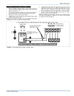
Typical Field Wiring (Air Handler / Electrical Heat) . . . . . . . . . . . . . . . .7
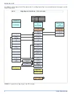
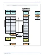
Thermostat Chart - Single Stage AC with PSC Air Handler . . . . . . . . .8
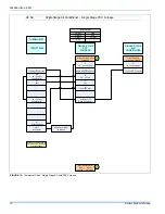
Thermostat Chart - Single Stage AC with PSC Air Handler . . . . . . . . .9
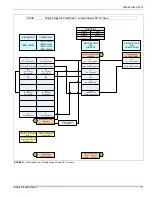
Thermostat Chart - Single Stage AC with PSC Furnace . . . . . . . . . .10
LIST OF TABLES
Application Limitations . . . . . . . . . . . . . . . . . . . . . . . . . . . . . . . . . . . . . 1
R-22 Saturated Properties . . . . . . . . . . . . . . . . . . . . . . . . . . . . . . . . . 6


