background image

Subject to change without notice. Printed in U.S.A.

290982-UIM-C-0907

Copyright

 ©

 by Unitary Products Group. 2007. All rights reserved.

Supersedes: 290982-UIM-B-0807

Unitary

5005

Norman

Product

York

OK

Group

Drive

73069

SECTION IX: INSTRUCTING THE OWNER

Assist owner with processing warranty cards and/or online registration.
Review Owners Guide and provide a copy to the owner and guidance
on proper operation and maintenance. Instruct the owner or the opera-
tor how to start, stop and adjust temperature setting.

When applicable, instruct the owner that the compressor is equipped
with a crankcase heater to prevent the migration of refrigerant to the
compressor during the “OFF” cycle. The heater is energized only when
the unit is not running. If the main switch is disconnected for long peri-
ods of shut down, do not attempt to start the unit until 8 hours after the
switch has been connected. This will allow sufficient time for all liquid
refrigerant to be driven out of the compressor.

The installer should also instruct the owner on proper operation and
maintenance of all other system components.

MAINTENANCE

1.

Dirt should not be allowed to accumulate on the outdoor coils or
other parts in the air circuit. Clean as often as necessary to keep
the unit clean. Use a brush, vacuum cleaner attachment, or other
suitable means.

2.

The outdoor fan motor is permanently lubricated and does not
require periodic oiling.

3.

If the coil needs to be cleaned, it should be washed with Calgon
Coilclean (mix one part Coilclean to seven parts water). Allow solu-
tion to remain on coil for 30 minutes before rinsing with clean water.
Solution should not be permitted to come in contact with painted
surfaces.

4.

Refer to the furnace or air handler instructions for filter and blower
motor maintenance.

5.

The indoor coil and drain pan should be inspected and cleaned reg-
ularly to prevent odors and assure proper drainage.

IT IS UNLAWFUL TO KNOWINGLY VENT, RELEASE OR DIS-
CHARGE REFRIGERANT INTO THE OPEN AIR DURING
REPAIR, SERVICE, MAINTENANCE OR THE FINAL DISPOSAL
OF THIS UNIT.
WHEN THE SYSTEM IS FUNCTIONING PROPERLY AND THE
OWNER HAS BEEN FULLY INSTRUCTED, SECURE THE
OWNER’S APPROVAL.

Summary of Contents for 13 SEER GCGD12

Page 1: ...des and the limitations listed below 1 Limitations for the indoor unit coil and appropriate accessories must also be observed 2 The outdoor unit must not be installed with any duct work in the air str...

Page 2: ...osition The base pad should not come in contact with the foun dation or side of the structure because sound may be transmitted to the residence The length of the refrigerant tubing between the outdoor...

Page 3: ...ions orifice connections system charging traps etc PRECAUTIONS DURING BRAZING OF LINES All outdoor unit and evaporator coil connections are copper to copper and should be brazed with a phosphorous cop...

Page 4: ...e System Charge section for checking and recording system charge Supplied with the outdoor unit is a Schrader Valve Core and Orifice for highest sales volume indoor coil The valve core must be install...

Page 5: ...bove 500 microns SECTION VII SYSTEM CHARGE The factory charge in the outdoor unit includes enough charge for the unit a 15 ft line set and the smallest indoor coil match up Some indoor coil matches ma...

Page 6: ...switch to the unit 4 Route wires from disconnect through power wiring opening pro vided and into the unit control box as shown in Figure 6 5 Install the proper size time delay fuses or circuit breake...

Page 7: ...o not place it on an out side wall or where it is exposed to the radiant effect from exposed glass or appliances drafts from outside doors or supply air grilles 6 Route the 24 volt control wiring NEC...

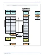
Page 8: ...ric heat on thermostat is not necessary MA SHP AHP ID MODELS Other Part Numbers SAP Legacy 265902 031 09167 2 Part Numbers SAP Legacy 159480 031 09156 1 COM 24 Volt Common R 24 Volt Hot W2 Second Stag...

Page 9: ...gle Stage Compressor Y Y2 Second or Full Stage Compressor W1 First Stage Heat Y Full Stage Compressor G Fan BP11C50124 BN11C01124 DP11C40124 DN11C00124 THERMOSTAT RH 24 Volt Hot Heat XFMR RC 24 Volt H...

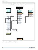
Page 10: ...G Fan SINGLE STAGE PSC FURNACE Y1 Single Stage Compressor Other Part Numbers SAP Legacy 265902 031 09167 1 1 HM1 Humidistat Y Full Stage Compressor G Fan PP11C70224 THERMOSTAT RH 24 Volt Hot Heat XFMR...

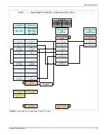
Page 11: ...ssary C 24 Volt Common Y Full Stage Compressor G Fan BN11C00124 THERMOSTAT RH 24 Volt Hot Heat XFMR RC 24 Volt Hot Cool XFMR W Full Stage Heat Thermostat Installer Setup 1 System Type must be set to 0...

Page 12: ...r The installer should also instruct the owner on proper operation and maintenance of all other system components MAINTENANCE 1 Dirt should not be allowed to accumulate on the outdoor coils or other p...

Reviews: