290982-UIM-C-0907
2
Unitary Products Group
SECTION III: UNIT INSTALLATION
LOCATION
Before starting the installation, select and check the suitability of the
location for both the indoor and outdoor unit. Observe all limitations and
clearance requirements.
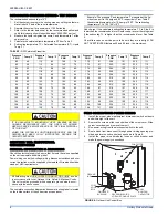
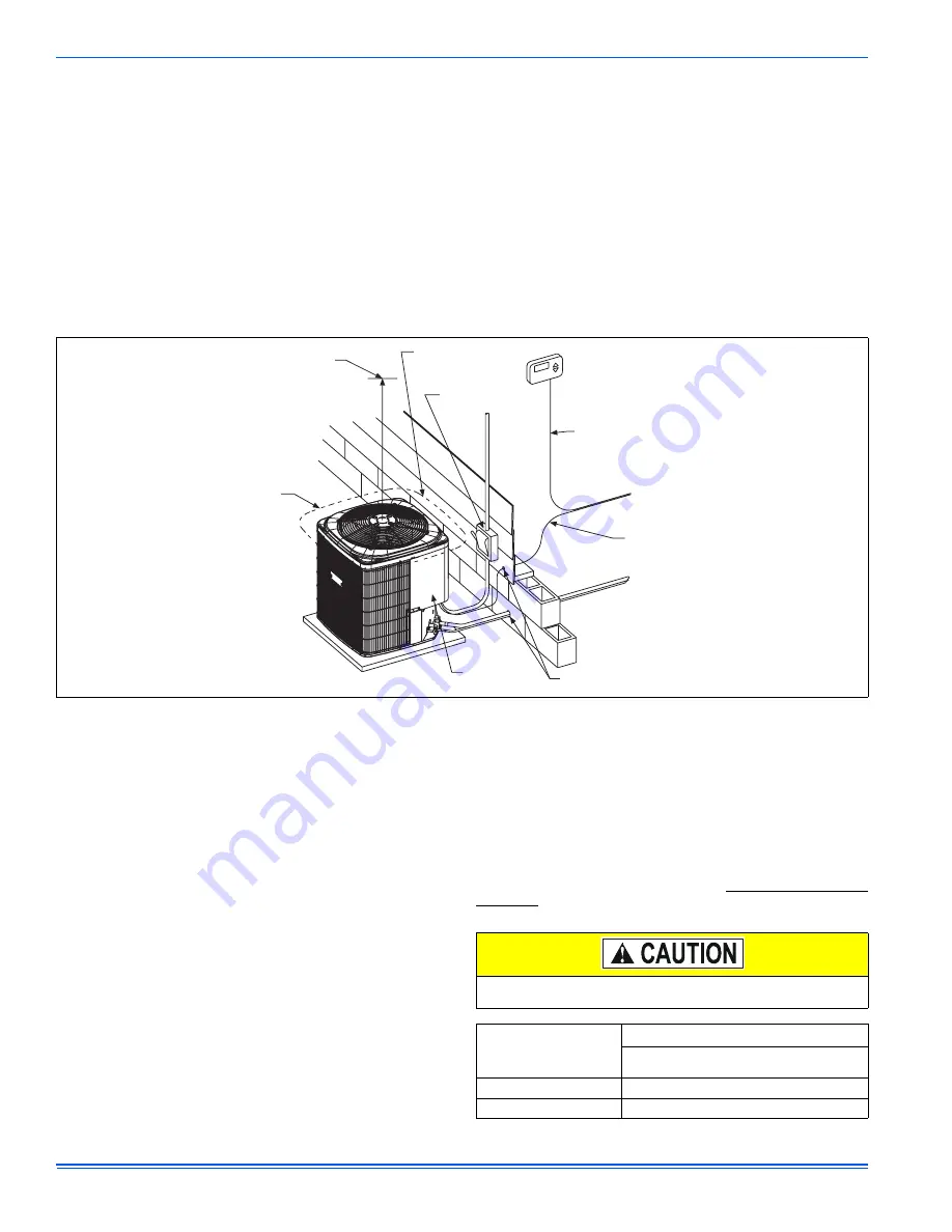
The outdoor unit must have sufficient clearance for air entrance to the
condenser coil, air discharge, and service access. See Figure 1.
NOTE:
For multiple unit installations, units must be spaced a minimum
of 18 inches apart (coil face to coil face).
If the unit is to be installed on a hot sun exposed roof or a black-topped
ground area, the unit should be raised sufficiently above the roof or
ground to avoid taking the accumulated layer of hot air into the outdoor
unit.
Provide an adequate structural support.
ADD-ON REPLACEMENT/RETROFIT
The following steps should be performed in order to insure proper sys-
tem operation and performance.
1.
Change-out the indoor coil, if required, to an approved R-22 coil/
condensing unit combination with the appropriate metering device.
2.
If the outdoor unit is being replaced due to a compressor burnout,
then installation of a 100% activated alumina suction-line filter
drier in the suction-line is required, in addition to the factory
installed liquid-line drier. Operate the system for 10 hours. Monitor
the suction drier pressure drop. If the pressure drop exceeds 3
psig, replace both the suction-line and liquid-line driers. After a
total of 10 hours run time where the suction-line pressure drop has
not exceeded 3 psig, replace the liquid line drier, and remove the
suction-line drier. Never leave a suction-line drier in the system
longer than 50 hours of run time.
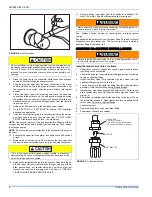
GROUND INSTALLATION
The unit should be installed on a solid base that is 2” above grade and
will not shift or settle, causing strain on the refrigerant lines and possible
leaks. Maintain the clearances shown in Figure 1 and install the unit in a
level position. The base pad should not come in contact with the foun-
dation or side of the structure because sound may be transmitted to the
residence.
The length of the refrigerant tubing between the outdoor unit and indoor
coil should be as short as possible to avoid capacity and efficiency
losses. Excessive spacing of the outdoor unit from the home can result
in the refrigerant lines being restricted by trampling or being punctured
by lawn mowers. Locate the outdoor unit away from bedroom windows
or other rooms where sound might be objectionable.
Adverse effects of snow or sleet accumulating on the outdoor coil can
be eliminated by placing the outdoor unit where the prevailing wind
does not blow across the unit. Trees, shrubs, corners of buildings, and
fences standing off from the coil can reduce capacity loss due to wind
chill effect.
Provide ample clearance from shrubs to allow adequate air to pass
across the outdoor coil without leaves or branches being pulled into the
coil.
ROOF INSTALLATION
When installing units on a roof, the structure must be capable of sup-
porting the total weight of the unit, including a pad, lintels, rails, etc.,
which should be used to minimize the transmission of sound or vibra-
tion into the conditioned space.
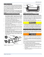
LIQUID LINE FILTER-DRIER
The air conditioning unit’s copper spun filter/dryer is located on the liq-
uid line.
NOTE: Replacements for the liquid line drier must be exactly the same
as marked on the original factory drier. See
Source 1 for O.E.M.
replacement driers.
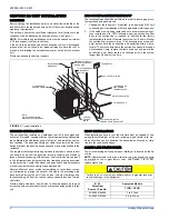
FIGURE 1:
Typical Installation
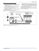
THERMOSTAT
SEAL OPENING(S) WITH
PERMAGUM OR EQUIVALENT
TO INDOOR COIL
TO FURNACE OR
AIR HANDLER
TERMINAL BLOCK
NEC CLASS 2 WIRING
NEC CLASS 1 WIRING
ALL OUTDOOR WIRING
MUST BE WEATHERPROOF.
CONTROL
ACCESS
PANEL
WEATHERPROOF
DISCONNECT
SWITCH
MINIMUM 18” SERVICE
ACCESS CLEARANCE
ON ONE SIDE
60” OVERHEAD
CLEARANCE
6” CLEARANCE
AROUND PERIMETER
NOTE:
Failure to do so or using a substitute drier or a granular type may
result in damage to the equipment.
R-22
Filter-Drier
Source 1 Part No.
Apply with Models
TCGD / GCGD
S1-02922156000
1 to 3 Tons
S1-02922157000
3.5 to 5 Tons


