290982-UIM-C-0907
4
Unitary Products Group
4.
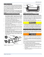
Braze the liquid line to the evaporator liquid connection. Nitrogen
should be flowing through the evaporator coil.
5.
Slide the grommet away from the vapor connection at the indoor
coil. Braze the vapor line to the evaporator vapor connection. After
the connection has cooled, slide the grommet back into original
position.
6.
Protect the vapor valve with a wet rag and braze the vapor line
connection to the outdoor unit. The nitrogen flow should be exiting
the system from the vapor service port connection. After this con-
nection has cooled, remove the nitrogen source from the liquid fit-
ting service port.
7.
Replace the Schrader core in the liquid and vapor valves.
8.
Go to “SECTION V” or “SECTION IV” for orifice or TXV installation
depending on application.
9.
Leak test all refrigerant piping connections including the service
port flare caps to be sure they are leak tight. DO NOT OVER-
TIGHTEN (between 40 and 60 inch - lbs. maximum).
NOTE:
Line set and indoor coil can be pressurized to 250 psig with dry
nitrogen and leak tested with a bubble type leak detector. Then release
the nitrogen charge.
NOTE:
Do not use the system refrigerant in the outdoor unit to purge or
leak test.
10. Evacuate the vapor line, evaporator, and liquid line to 500 microns
or less.
11.
Replace cap on service ports. Do not remove the flare caps from
the service ports except when necessary for servicing the system.
12. Release the refrigerant charge into the system. Open both the liq-
uid and vapor valves by removing the plunger cap and with an
allen wrench back out counter-clockwise until valve stem just
touches the chamfered retaining wall. See Page 3 "PRECAU-
TIONS DURING BRAZING SERVICE VALVE".
13. Replace plunger cap finger tight, then tighten an additional 1/12
turn (1/2 hex flat). Cap must be replaced to prevent leaks.
See "System Charge” section for checking and recording system
charge.
Supplied with the outdoor unit is a Schrader Valve Core and Orifice for
highest sales volume indoor coil. The valve core must be installed in
equalizer fitting of the indoor coil.
SECTION IV: ORIFICE INSTALLATION
Install Schrader Valve Core as follows:
1.
Slide indoor coil out of cabinet far enough to gain access to equal-
izer fitting on the suction line.
2.
After holding charge is completely discharged remove black plas-
tic cap on equalizer fitting.
3.
Install Schrader Valve Core supplied with the outdoor unit into
equalizer fitting using a valve core tool.
4.
Loosen and remove the liquid line fitting from the orifice distributor
assembly. Note that the fitting has right hand threads.
5.
Install proper size orifice supplied with outdoor unit. Refer to sup-
plied Tabular Data Sheet for specific orifice size and indoor coil
match up.
6.
After orifice is installed reinstall the liquid line to the top of the ori-
fice distributor assembly. Hand tighten and turn an additional 1/8
turn to seal. Do not over tighten fittings.
7.
Leak test system.
8.
Replace black plastic cap on equalizer fitting.
9.
Slide indoor coil back into cabinet.
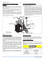
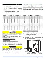
FIGURE 4:
Heat Protection
Do not install any coil in a furnace which is to be operated during
the heating season without attaching the refrigerant lines to the coil.
The coil is under 30 to 35 psig inert gas pressure which must be
released to prevent excessive pressure build-up and possible coil
damage.
Do not connect manifold gauges unless trouble is suspected.
Approximately 3/4 ounce of refrigerant will be lost each time a stan-
dard manifold gauge is connected.
Never attempt to repair any brazed connections while the system is
under pressure. Personal injury could result.
Failure to install Schrader Valve Core on orifice applications could
result in total refrigerant loss of the system!
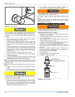
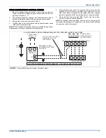
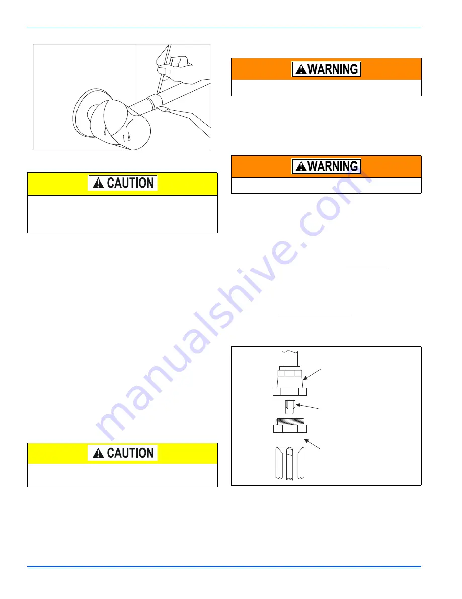
FIGURE 5:
Orifice Installation
LIQUID LINE
SWIVEL COUPLING
(This fitting is a right-hand thread,
turn counter-clockwise to remove)
ORIFICE
DISTRIBUTOR


