290982-UIM-C-0907
Unitary Products Group
5
SECTION V: TXV INSTALLATIONS
The following are the basic steps for installation. For detailed instruc-
tions, refer to the Installation Instructions accompanying the TXV kit.
Install TXV kit as follows:
1.
Relieve the holding charge by pulling off the rubber cap plug on
the suction manifold line of the coil.
2.
After holding charge is completely discharged, loosen and remove
the schraeder cap seal.
3.
Loosen and remove distributor cap seal.
4.
Install the thermal expansion valve to the orifice distributor assem-
bly with supplied fittings. Hand tighten and turn an additional 1/4
turn to seal. Do not overtighten fittings.
5.
Install the liquid line to the top of the thermal expansion valve with
fitting supplied with the liquid line. Hand modify the liquid line to
align with casing opening. Hand tighten the liquid line and an addi-
tional 1/4 turn to seal.
6.
Install the TXV equalizer line into the vapor line as follows:
a.
Hand tighten the 1/4” SAE nut to the schraeder fitting and an
additional 1/3 turn to seal.
7.
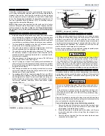
Install the TXV bulb to the vapor line near the equalizer line, using
the bulb clamp(s) furnished with the TXV assembly. Ensure the
bulb is making maximum contact.
a.
Bulb should be installed on a horizontal run of the vapor line if
possible. The bulb should be installed on top of the line.
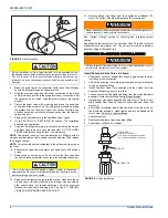
b.
If bulb installation is made on a vertical run, the bulb should
be located at least 16 inches from any bend, and on the tub-
ing sides opposite the plane of the bend. The bulb should be
positioned with the bulb tail at the top, so that the bulb acts as
a reservoir.
c.
Bulb should be insulated using thermal insulation provided to
protect it from the effect of the surrounding ambient tempera-
ture. Cover completely to insulate from air-stream.
SECTION VI: EVACUATION
It will be necessary to evacuate the system to 500 microns or less. If a
leak is suspected, leak test with dry nitrogen to locate the leak. Repair
the leak and test again.
To verify that the system has no leaks, simply close the valve to the vac-
uum pump suction to isolate the pump and hold the system under vac-
uum. Watch the micron gauge for a few minutes. If the micron gauge
indicates a steady and continuous rise, it’s an indication of a leak. If the
gauge shows a rise, then levels off after a few minutes and remains
fairly constant, it’s an indication that the system is leak free but still con-
tains moisture and may require further evacuation if the reading is
above 500 microns.
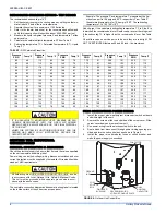
SECTION VII: SYSTEM CHARGE
The factory charge in the outdoor unit includes enough charge for the
unit, a 15 ft. line set, and the smallest indoor coil match-up. Some
indoor coil matches may require additional charge. See tabular data
sheet provided in unit literature packet for charge requirements.
The “TOTAL SYSTEM CHARGE” must be permanently stamped on the
unit data plate.
Total system charge is determined as follows:
1.
Determine outdoor unit charge from tabular data sheet.
2.
Determine indoor coil adjustment from tabular data sheet.
3.
Calculate the line charge using the tabular data sheet if line length
is greater than 15 feet.
4.
Total system charge = item 1 + item 2 + item 3.
5.
Permanently stamp the unit data plate with the total amount of
refrigerant in the system.
Use the following charging method whenever additional refrigerant is
required for the system charge.
If a calibrated charging cylinder or accurate weighing device is avail-
able, add refrigerant accordingly. Otherwise, model-specific charging
charts are provided on the access panel of the unit.
SUPERHEAT CHARGING METHOD -
PISTON INDOOR
1.
Operate system until temperatures and pressures stabilize (mini-
mum of 10 minutes).
2.
Measure and record indoor wet bulb (WB) temperature using a
sling psychrometer and the outdoor dry bulb (DB) temperature
using a thermometer.
3.
Measure and record the suction pressure at the suction service
valve port.
4.
Using charts located on the unit, note the superheat value corre-
sponding to the intersection of the indoor wet bulb and the outdoor
dry bulb.
5.
With the superheat value obtained in step 4 and the suction pres-
sure value from step 3, find the intersection of the values on the
chart. This is the required suction tube temperature at the suction
service valve.
6.
To bring the tube temperature in line with the required value from
chart, add refrigerant to the service port to cause the tube temper-
ature to fall and reclaim refrigerant to cause the temperature to
rise.
When using a TXV, models 12-48 require a hard start kit. Models
12-48 with a “H” on the end of the model number have a factory
installed hard start.
In all cases, mount the TXV bulb after vapor line is brazed and has
had sufficient time to cool.
Schrader valve core MUST NOT be installed with TXV installation.
Poor system performance or system failure could result.
Do not leave the system open to the atmosphere.
Refrigerant charging should only be carried out by a qualified air
conditioning contractor.
Compressor damage will occur if system is improperly charged. On
new system installations, charge system per tabular data sheet for
the matched coil and follow guidelines in this instruction.


