290982-UIM-C-0907
6
Unitary Products Group
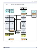
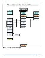
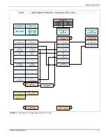
SUBCOOLING CHARGING METHOD - TXV INDOOR
The recommended subcooling is 10°F
1.
Set the system running in the cooling mode by setting the thermo-
stat at least 6°F below the room temperature.
2.
Operate the system for a minimum of 15-20 minutes.
3.
Refer to the tabular data sheet for the recommended airflow and
verify this indoor airflow (it should be about 400 SCFM per ton).
4.
Measure the liquid refrigerant pressure P and temperature T at the
service valve.
5.
Calculate the saturated liquid temperature ST from Table 2.
6.
Subcooling temperature TC = Saturated Temperature (ST) - Liquid
Temp (T).
Add charge if the calculated subcooling temperature TC in Step 6 is
lower than the recommended level. Remove and recover the refrigerant
if the subcooling TC is higher than the recommended level. See Table
2.
Check flare caps on service ports to be sure they are leak tight. DO
NOT OVERTIGHTEN (between 40 and 60 inch - lbs. maximum).
SECTION VIII: ELECTRICAL
CONNECTIONS
GENERAL INFORMATION & GROUNDING
Check the electrical supply to be sure that it meets the values specified
on the unit nameplate and wiring label.
Power wiring, control (low voltage) wiring, disconnect switches and over
current protection must be supplied by the installer. Wire size should be
sized per NEC requirements.
The complete connection diagram and schematic wiring label is located
on the inside surface of the unit service access panel.
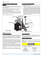
FIELD CONNECTIONS POWER WIRING
1.
Install the proper size weatherproof disconnect switch outdoors
and within sight of the unit.
2.
Remove the screws at the top and sides of the corner cover. Slide
corner cover down and remove from unit.
3.
Run power wiring from the disconnect switch to the unit.
4.
Route wires from disconnect through power wiring opening pro-
vided and into the unit control box as shown in Figure 6.
5.
Install the proper size time-delay fuses or circuit breaker, and
make the power supply connections.
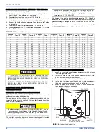
Example: The pressure P and temperature T measured at the liq-
uid service port is 196 psig and 90°F, respectlvely. From Table 2,
the saturated temperature for 196 psig is 100°F. The subcooling
temperature TC = 100°-90°=10°F
TABLE 2:
R-22 Saturated Properties
Pressure
PSIG
Temp °F
Pressure
PSIG
Temp °F
Pressure
PSIG
Temp °F
Pressure
PSIG
Temp °F
Pressure
PSIG
Temp °F
Pressure
PSIG
Temp °F
80
48
110
64
140
78
170
91
200
101
230
111
82
49
112
65
142
79
172
91
202
102
232
112
84
50
114
66
144
80
174
92
204
103
234
112
86
51
116
67
146
81
176
93
206
103
236
113
88
52
118
68
148
82
178
94
208
104
238
114
90
54
120
69
150
83
180
94
210
105
240
114
92
55
122
70
152
84
182
95
212
105
242
115
94
56
124
71
154
84
184
96
214
106
244
115
96
57
126
72
156
85
186
97
216
107
246
116
98
58
128
73
158
86
188
97
218
107
248
117
100
59
130
74
160
87
190
98
220
108
250
117
102
60
132
75
162
88
192
99
222
109
252
118
104
61
134
76
164
88
194
99
224
109
254
118
106
62
136
77
166
89
196
100
226
110
256
119
108
63
138
78
168
90
198
101
228
111
258
119
IT IS UNLAWFUL TO KNOWINGLY VENT, RELEASE OR DIS-
CHARGE REFRIGERANT INTO THE OPEN AIR DURING
REPAIR, SERVICE, MAINTENANCE OR THE FINAL DISPOSAL
OF THIS UNIT.
WHEN THE SYSTEM IS FUNCTIONING PROPERLY AND THE
OWNER HAS BEEN FULLY INSTRUCTED, SECURE THE
OWNER’S APPROVAL.
All field wiring must USE COPPER CONDUCTORS ONLY and be
in accordance with Local, National, Fire, Safety & Electrical Codes.
This unit must be grounded with a separate ground wire in accor-
dance with the above codes.
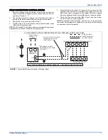
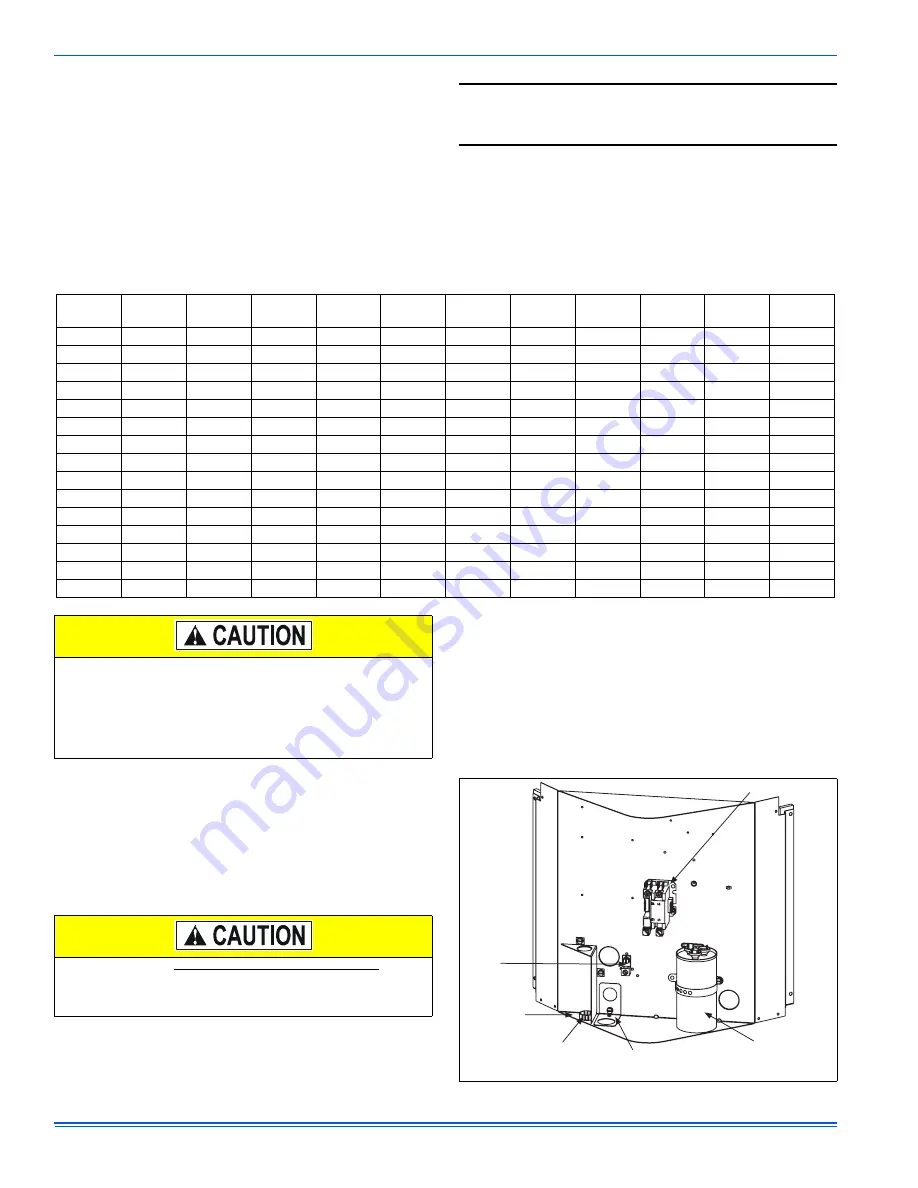
FIGURE 6:
Outdoor Unit Control Box
GROUND
LUG
“FINGERED”
BUSHING
LOW
VOLTAGE
BOX
REVERSIBLE HIGH
VOLTAGE CONDUIT PLATE
DUAL
RUN/FAN
CAPACITOR
CONTACTOR


