background image

290982-UIM-C-0907

Unitary Products Group

7

FIELD CONNECTIONS CONTROL WIRING

1.

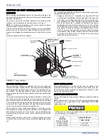
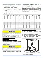
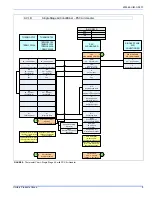
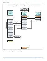
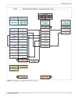
Route low voltage wiring into bottom of control box as shown in
Figure 6. Make low voltage wiring connections inside the low volt-
age box per Figures 7 - 11.

2.

The complete connection diagram and schematic wiring label is
located on the inside surface of the unit service access panel.

3.

Replace the corner cover removed in Step 2.

4.

All field wiring to be in accordance with national electrical codes
(NEC) and/or local-city codes.

NOTE: 

A Start Assist Kit is available and recommended for long line set

applications or in areas of known low voltage problems.

5.

Mount the thermostat about 5 ft. above the floor, where it will be
exposed to normal room air circulation. Do not place it on an out-
side wall or where it is exposed to the radiant effect from exposed
glass or appliances, drafts from outside doors or supply air grilles.

6.

Route the 24-volt control wiring (NEC Class 2) from the outdoor
unit to the indoor unit and thermostat.

NOTE: 

To eliminate erratic operation, seal the hole in the wall at the

thermostat with permagum or equivalent to prevent air drafts affecting
the operation of in the thermostat.
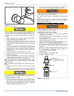
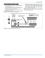
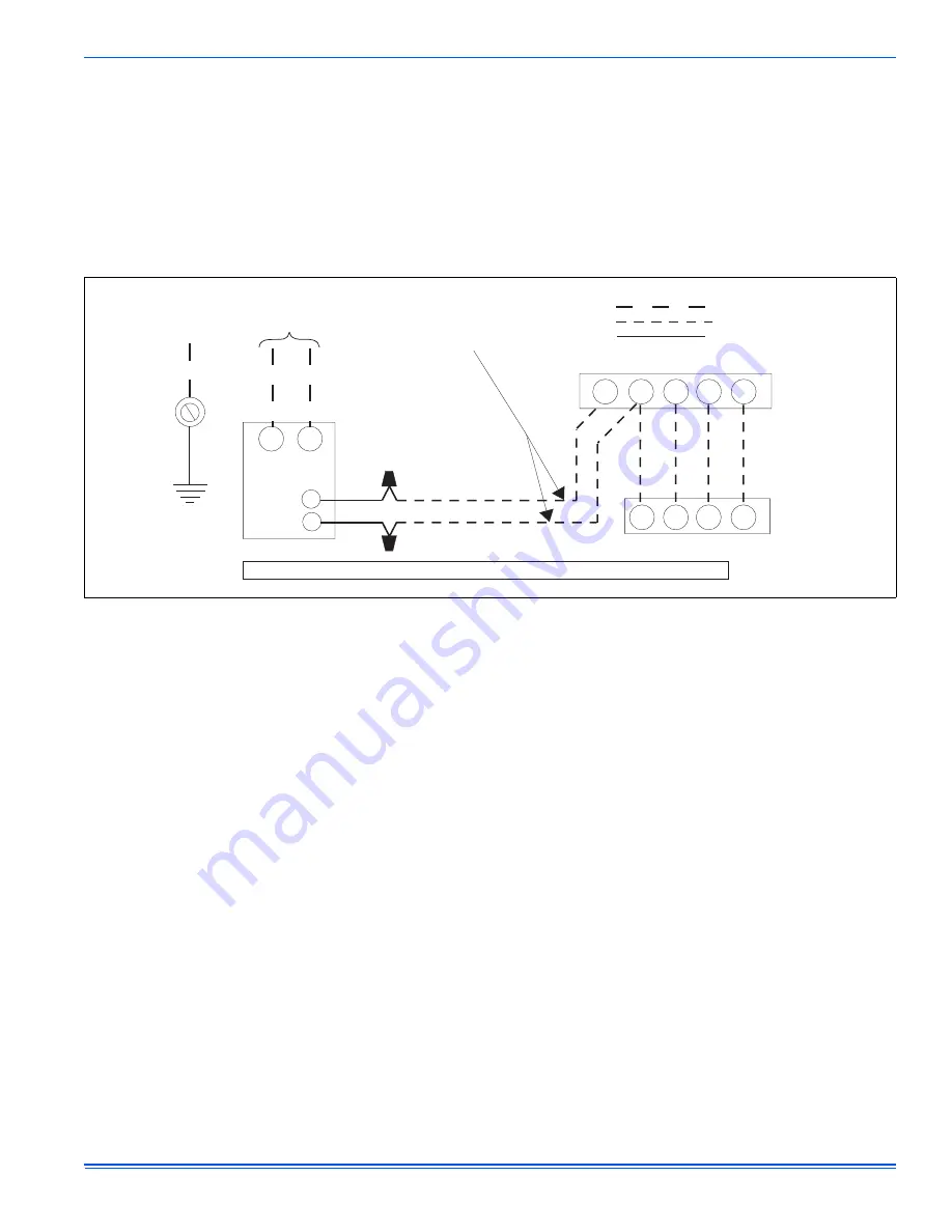
 FIGURE 7:  

Typical Field Wiring (Air Handler / Electrical Heat)

ALL FIELD WIRING TO BE IN ACCORDANCE WITH ELECTRIC CODE (NEC) AND/OR LOCAL CODES

POWER WIRING

208/230-1-60

CONTACTOR
TERMINALS

COIL

GND.

LUG

C

Y

R

G

W

Y

R

G

W

POWER WIRING
CONTROL WIRING

FACTORY WIRING

24 VOLT CONTROL WIRING
MINIMUM 18 GA. WIRE
(NEC CLASS 2)

FURNACE OR AIR HANDLER TERMINAL BLOCK

ROOM THERMOSTAT

CONDENSING UNIT

ALL OUTDOOR WIRING MUST BE WEATHERPROOF. USE COPPER CONDUCTORS ONLY.

TERMINAL W IS ONLY
REQUIRED ON SYSTEMS
WITH HEAT.

*

*

Summary of Contents for 13 SEER GCGD12

Page 1: ...des and the limitations listed below 1 Limitations for the indoor unit coil and appropriate accessories must also be observed 2 The outdoor unit must not be installed with any duct work in the air str...

Page 2: ...osition The base pad should not come in contact with the foun dation or side of the structure because sound may be transmitted to the residence The length of the refrigerant tubing between the outdoor...

Page 3: ...ions orifice connections system charging traps etc PRECAUTIONS DURING BRAZING OF LINES All outdoor unit and evaporator coil connections are copper to copper and should be brazed with a phosphorous cop...

Page 4: ...e System Charge section for checking and recording system charge Supplied with the outdoor unit is a Schrader Valve Core and Orifice for highest sales volume indoor coil The valve core must be install...

Page 5: ...bove 500 microns SECTION VII SYSTEM CHARGE The factory charge in the outdoor unit includes enough charge for the unit a 15 ft line set and the smallest indoor coil match up Some indoor coil matches ma...

Page 6: ...switch to the unit 4 Route wires from disconnect through power wiring opening pro vided and into the unit control box as shown in Figure 6 5 Install the proper size time delay fuses or circuit breake...

Page 7: ...o not place it on an out side wall or where it is exposed to the radiant effect from exposed glass or appliances drafts from outside doors or supply air grilles 6 Route the 24 volt control wiring NEC...

Page 8: ...ric heat on thermostat is not necessary MA SHP AHP ID MODELS Other Part Numbers SAP Legacy 265902 031 09167 2 Part Numbers SAP Legacy 159480 031 09156 1 COM 24 Volt Common R 24 Volt Hot W2 Second Stag...

Page 9: ...gle Stage Compressor Y Y2 Second or Full Stage Compressor W1 First Stage Heat Y Full Stage Compressor G Fan BP11C50124 BN11C01124 DP11C40124 DN11C00124 THERMOSTAT RH 24 Volt Hot Heat XFMR RC 24 Volt H...

Page 10: ...G Fan SINGLE STAGE PSC FURNACE Y1 Single Stage Compressor Other Part Numbers SAP Legacy 265902 031 09167 1 1 HM1 Humidistat Y Full Stage Compressor G Fan PP11C70224 THERMOSTAT RH 24 Volt Hot Heat XFMR...

Page 11: ...ssary C 24 Volt Common Y Full Stage Compressor G Fan BN11C00124 THERMOSTAT RH 24 Volt Hot Heat XFMR RC 24 Volt Hot Cool XFMR W Full Stage Heat Thermostat Installer Setup 1 System Type must be set to 0...

Page 12: ...r The installer should also instruct the owner on proper operation and maintenance of all other system components MAINTENANCE 1 Dirt should not be allowed to accumulate on the outdoor coils or other p...

Reviews: