035-18547-001-A-0902
18
Unitary Products Group
10. Is any electrical wire laying against a hot refrigerant
line? Keep in mind that this unit has a reverse
cycle and that different lines will be hot during the
“HEAT” and “COOL” cycles. Only two lines will
remain cool for all cycles - the line between the
compressor and the accumulator and the line
between the accumulator and the reversing valve.
INITIAL START-UP
1.
Supply power to the unit through the disconnect
switch prior to starting the compressor.
2.
Move the system switch on the room thermostat to
the “COOL” position, and lower its set point to
energize both the compressor and the reversing
valve. Cool air will be supplied to the conditioned
space.
3.
Check the compressor amperage. It should not
exceed the RLA rating printed on the unit data
plate or in Table 3 unless the ambient temperature
is above 105°F.
4.
Move the system switch on the room thermostat to
the “HEAT” position, and increase the set point of
the room thermostat until heating is required. The
compressor will run, but the reversing valve will be
de-energized. Warm air will be supplied to the con-
ditioned space.
5.
Check the operation of the indoor unit per Form
515.41-N2.
6.
Check the entire system for refrigerant leaks.
7.
Check for any abnormal noises and/or vibrations,
and make the necessary adjustments to correct
(e.g. fan blade touching shroud, refrigerant lines
hitting on sheet metal, etc.)
8.
After the unit has been operating for several min-
utes, shut off the main power supply at the discon-
nect switch and inspect all factory wiring
connections and bolted surfaces for tightness.
OPERATION
GENERAL
During the cooling cycle, when the reversing valve
solenoid becomes energized, operation will be the
same as any conventional air conditioning system.
During the heating cycle, when the reversing valve
solenoid becomes de-energized, compressor dis-
charge gas will be diverted to the indoor coil and the
outdoor coil will become the evaporator.
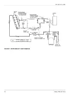
Refer to Figure 7 for illustration showing the flow of
refrigerant through a heat pump system.
SYSTEM SEQUENCE OF OPERATION
The following sequences of operation are based on
using the manual changeover thermostat. Refer to the
respective unit wiring diagram.
COOLING OPERATION
1.
The following controls will be energized through
terminal O on the thermostat to put the system in
the cooling mode.
• Relay RW and reversing valve solenoid.
2.
If the fan switch on the thermostat is in the “ON”
position, indoor section blower motor contactor
10M will be energized through terminal G to pro-
vide continuous blower operation. If the switch is in
the “AUTO” position, the blower will operate only
when the thermostat calls for cooling operation.
3.
When TC1 of the thermostat closes on a demand
for cooling, a circuit is made from terminal Y
through the defrost control board and safety
switches to energize contactor 1M and relay RY1,
starting the compressor. Contactor 2M is energized
through the NO contacts of RY1-1 and the NC con-
tacts of K2 on the defrost control board in order to
start the outdoor fan motor(s).
NOTE:
If discharge pressure falls below 180 PSI, PS
will open and de-energize No. 2 fan motor.
Reversing valves and check valves are precise
mechanical devices and will not tolerate any
mechanical abuse such as hammering. If a
refrigerant system isn't properly cleaned after a
compressor burn-out, scale may build up at
these devices and prevent them from operating
properly.


