background image

CONTENTS

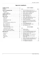
GENERAL  . . . . . . . . . . . . . . . . . . . . . . . . . . . . . . . . . . 4

SAFETY CONSIDERATIONS  . . . . . . . . . . . . . . . . . . . 4

AGENCY APPROVALS . . . . . . . . . . . . . . . . . . . . . . . . 4

INSPECTION  . . . . . . . . . . . . . . . . . . . . . . . . . . . . . . . . 4

INSTALLATION . . . . . . . . . . . . . . . . . . . . . . . . . . . . . . 6

MAINTENANCE . . . . . . . . . . . . . . . . . . . . . . . . . . . . . 18

See the following page for a complete Table of Contents.

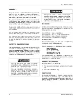
NOTES, CAUTIONS AND WARNINGS

Installer should pay particular attention to the words: 

NOTE

,

CAUTION

, and 

WARNING

. Notes are intended to clarify or

make the installation easier. Cautions are given to prevent
equipment damage. Warnings are given to alert installer
that personal injury and/or equipment damage may result if
installation procedure is not handled properly.

INSTALLATION 
MANUAL

CAUTION:

READ ALL SAFETY GUIDES BEFORE YOU 
BEGIN TO INSTALL YOUR UNIT.

SAVE THIS MANUAL

035-18877-001-B-0203

SPLIT-SYSTEM HEAT PUMPS 

INDOOR UNITS

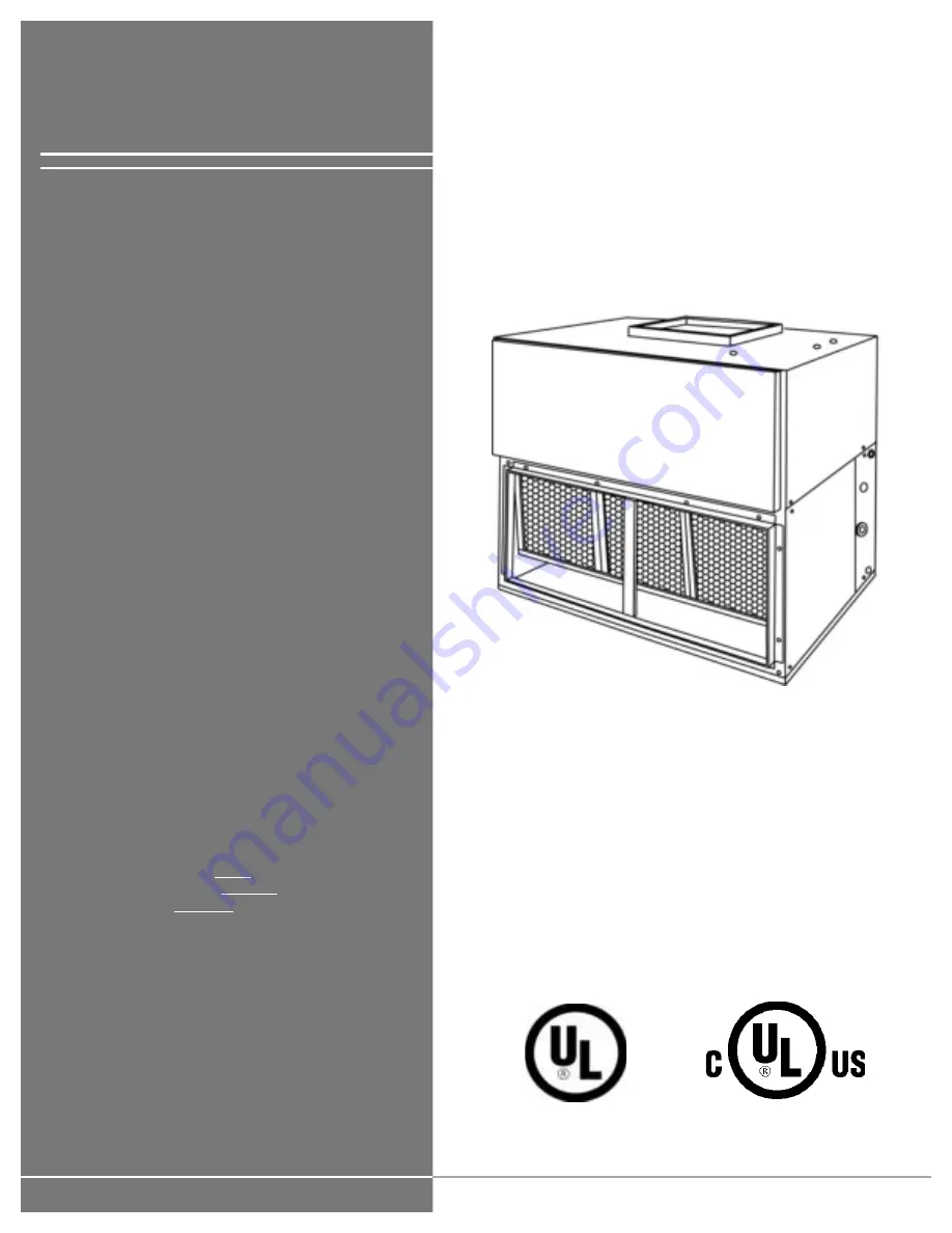
MODEL:  FF-10

Summary of Contents for FF-10

Page 1: ...CAUTION and WARNING Notes are intended to clarify or make the installation easier Cautions are given to prevent equipment damage Warnings are given to alert installer that personal injury and or equip...

Page 2: ...PPLICATION 7 3 SUPPLY AIR DUCT CONNECTIONS 8 4 ELECTRIC HEAT ACCESSORY 8 5 RETURN AIR GRILLE FF 10 9 6 BASE ACCESSORY FF 10 9 7 SUPPLY AIR PLENUM FF 10 9 8 SUPPLY AIR PLENUM KNOCKOUTS FF 10 9 9 RECOMM...

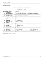
Page 3: ...entifier F R 22 Standard Efficiency 2 Pipe L R 22 Standard Efficiency 4 Pipe 10 Nominal Cooling Capacity MBH 07 7 1 2 Ton 10 10 Ton 15 15 Ton 20 20 Ton C Heat Type C Cooling Only 00 Nominal Heating Ca...

Page 4: ...is available in the following reference forms Form 55 70 N1 General Installation Form 55 70 N2 Pre start Post start Check List Form 55 70 N3 General Service Information Form 55 05 NM Evacuation and Ch...

Page 5: ...SHIPPING 425 OPERATING 435 ACCESSORY OPERATING WEIGHT LBS MOTOR 2 HP ELECTRIC HEAT 10 KW 63 16 KW 66 26 KW 71 36 KW 74 SUPPLY AIR PLENUM 114 RETURN AIR GRILLE 20 BASE 100 TABLE 2 UNIT APPLICATION DAT...

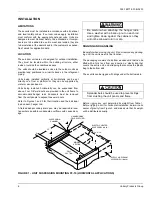
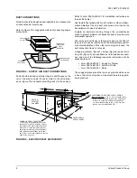
Page 6: ...eld nuts Refer to Figures 1 and 3 for their location and the individual load on each hanger rod A field added secondary drain pan may be required in loca tions where possible condensate overflow could...

Page 7: ...ction 2 Remove the four Phillips machine bolts that hold the coil and blower sections together A bolt is located near each corner 3 Move the blower section to the proper location 4 Attach the blower s...

Page 8: ...field installed accesso ries and one of the following respective instructions will be packed with each Form 035 16650 001 Supply Air Plenum Form 035 16621 001 Return Air Grille Form 035 16632 001 Base...

Page 9: ...ETURN AIR GRILLE FF 10 FIGURE 6 BASE ACCESSORY FF 10 60 3 4 31 5 8 24 31 5 8 60 3 4 BASE FIGURE 7 SUPPLY AIR PLENUM FF 101 1 Electric Heaters are NOT UL approved for installation within a SUPPLY AIR P...

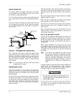
Page 10: ...angers brackets or clamps Braze all copper to copper joints with Sil Fos 5 or equivalent brazing material DO NOT USE SOFT SOLDER Never braze or solder the liquid and vapor lines together for support p...

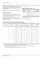
Page 11: ...Supply FLA Max Fuse Size1 AMPS 1 Dual element time delay fuses 2 208 3 60 7 5 15 230 3 60 6 8 15 460 3 60 3 4 15 Note Refer to Form 035 16602 001 for electrical data on units equipped with an electri...

Page 12: ...__________ 2 Indoor Unit to Thermostat _____________ 3 Thermostat to Indoor Unit _____________ 4 Indoor Unit to Outdoor Unit _____________ 5 Outdoor Unit to Elec Heater _____________ Total Circuit Len...

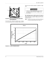
Page 13: ...the mounting plate and retighten after the mount ing plate has been moved to the proper position NOTE Never loosen the two nuts C shown in Figure 11 4 All pulleys are factory aligned 5 All supply air...

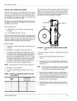
Page 14: ...029 13880 000 are available through Source One Parts ordering procedures NOTE Shut down the heat pump system before taking any test measurements to assure a dry indoor coil FIGURE 12 HOLE LOCATIONS FO...

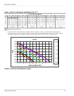
Page 15: ...n 2 turns 3 turns 4 turns 5 turns Exceeds Amperage rating of motor 1 Motors can be selected to operate into the service factor because they are located in the moving air stream upstream of any heating...

Page 16: ...Air Plenum 0 05 0 06 0 07 0 08 0 10 Return Air Grille 0 05 0 06 0 07 0 08 0 10 TABLE 10 BLOWER MOTOR DRIVE DATA Model Motor HP1 Blower RPM Adjustable Motor Pulley Fixed Blower Pulley Belt Pitch Dia In...

Page 17: ...s s o r y f o r p o w e r w i r i n g a c c e s s o p e n i n g 7 8 K N O C K O U T F O R C O N T R O L W I R I N G A L T E R N A T E 2 5 8 K N O C K O U T R e f e r t o I N S T A L L I N G R E F R I...

Page 18: ...recommended to prevent any loss in capacity and efficiency FILTERS The filters must be replaced as often as necessary to assure good air flow and filtering action Clean filters will prevent any loss...

Page 19: ...035 18877 001 B 0203 Unitary Products Group 19...

Page 20: ...o change without notice Printed in U S A 035 18877 001 B 0203 Copyright by Unitary Products Group 2003 All rights reserved Supersedes 035 18877 001 A 0802 Unitary 5005 Norman Products York OK Group Dr...

Reviews: