66832-UIM-D-1205
6
Unitary Products Group
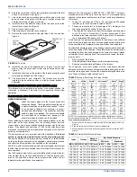
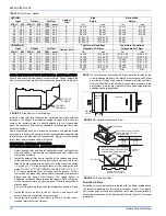
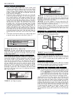
10. Rotate the vent blower 180º so that its outlet points toward the inlet
air end of the furnace. See Figure 2.
11.
Line up the vent blower mounting holes with the holes in the vent
pan and screw it into place. Use the same machine screws that
held the vent blower in place previously.
12. Install the two extra machine screws in the two open holes in the
front of the vent pan. See Figure 2.
13. Plug in the vent motor wires.
14. Plug the pressure hose into the vent blower.
15. Remove the round knockout at the right side of the top cap. See
Figure 4.
16. Install the top cap at the opposite end of furnace from the vent
blower, using the seven sheet metal screws saved earlier. See
Figure
2.
17. Install the bottom cap on the bottom of the furnace using the sheet
metal screws saved earlier. See Figure 2.
18. The conversion is now complete. The furnace may now be
installed in the downflow position or in the horizontal position on
either side.
INSTALLATION POSITION (150 MBH Models)
This furnace may be installed in an upflow or horizontal position. No
conversion is necessary. This furnace is not approved for downflow
application.
FLOOR BASE AND DUCTWORK INSTALLATION
Upflow Instructions
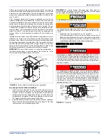
Attach the supply plenum to the furnace outlet duct
connection flanges. This is typically through the use of
S cleat material when a metal plenum is used. The use
of an approved flexible duct connector is recom-
mended on all installations. This connection should be
sealed to prevent air leakage. The sheet metal should
be cross-hatched to eliminate any popping of the
sheet metal when the indoor fan is energized.
When replacing an existing furnace, if the existing plenum is not the
same size as the new furnace then the existing plenum must be
removed and a new plenum installed that is the proper size for the new
furnace. If the plenum is shorter than 12” (30.5 cm) the turbulent air flow
may cause the limit controls not to operate as designed, or the limit con-
trols may not operate at all.
The duct system is a very important part of the installation. If the duct
system is improperly sized the furnace will not operate properly.
The ducts attached to the furnace plenum, should be of sufficient size
so that the furnace operates at the specified external static pressure
and within the air temperature rise specified on the nameplate.
Table 2 is a guide for determining whether the rectangular duct system
that the furnace is being connected to be of sufficient size for proper fur-
nace operation.
Use the Example below to help you in calculating the duct area to deter-
mine whether the ducts have sufficient area so that the furnace oper-
ates at the specified external static pressure and within the air
temperature rise specified on the nameplate.
Example: The furnace input is 80,000 BTUH, 1,200 CFM. The recom-
mended duct area is 280 sq.in, there are two 8 x 14 rectangular ducts
attached to the plenum and there are two 7 inch round ducts attached to
the furnace.
1.
Take 8 x 14, which equals 112 sq.in. X 2, which equals 224 square
inch then go to round duct size located in Table 2.
2.
The square inch area for 7 inch round pipe is 38.4, multiply by 2 for
two round ducts which equals 76.8 square inch.
3.
Then take the 224 square inch from the rectangular duct and add it
to the 76.8 sq.in. of round duct. The total square inch of duct
attached to the furnace plenum is 300.8 square inch. This exceeds
the recommended 280 square inch of duct.
In this example, the duct system attached to the plenum has a sufficient
area so that the furnace operates at the specified external static pres-
sure and within the air temperature rise specified on the nameplate.
Consideration should be given to the heating capacity required and also
to the air quantity (CFM) required. These factors can be determined by
calculating the heat loss and heat gain of the home or structure. If these
calculations are not performed and the furnace is over-sized, the follow-
ing may result:
1.
Short cycling of the furnace.
2.
Wide temperature fluctuations from the thermostat setting.
3.
Reduced overall operating efficiency of the furnace.
The supply and return duct system must be of adequate size and
designed such that the furnace will operate within the designed air tem-
perature rise range and not exceed the maximum designed static pres-
sure. These values are listed Tables 2 and 3.
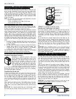
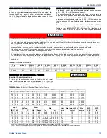
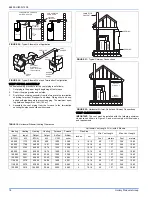
FIGURE 4: Top Cap
UPFLOW
VENT
OPENING
DOWNFLOW
VENT
OPENING
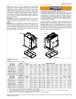
TABLE 2: Minimum Duct Sizing For Proper Airflow
Input
Airflow
Return
1
1. Maximum return air velocity in rigid duct @ 700 feet per minute (19.82 m
3
/
minute).
Rectangular
2
2. Example return main trunk duct minimum dimensions.
Round
2
Supply
3
3. Maximum supply air velocity in rigid duct @ 900 feet per minute (25.49 m
3
/
minute).
BTU/H
(kW)
CFM
(m³)
In²
(cm²)
in. x in.
(cm x cm)
in.
(cm) dia.
In²
(cm²)
50000
(14.65)
1,200
(33.98)
280
(711)
14 x 20
(35.6 x 50.8)
18
(45.7)
216
(549)
75000
(21.98)
1,200
(33.98)
280
(711)
14 x 20
(35.6 x 50.8)
18
(45.7)
216
(549)
75000
(21.98)
1,600
(45.31)
360
(914)
18 x 20
(45.7 x 50.8))
22
(55.8)
280
(711)
100000
(29.31)
1,600
(45.31)
360
(914)
18 x 20
(45.7 x 50.8)
22
(55.8)
280
(711)
100000
(29.31)
2,000
(56.63)
440
(1,118)
20 x 22
(50.8 x 55.8)
24
(60.9)
390
(991)
125000
(36.63)
2,000
(56.63)
440
(1,118)
20 x 22
(50.8 x 55.8)
24
(60.9)
390
(991)
150000
(43.96)
2,000
(56.63)
440
(1,118)
20 x 22
(50.8 x 55.8)
24
(60.9)
390
(991)
NOTE: This chart does not replace proper duct sizing calculations or take into
account static pressure drop for run length and fittings. Watch out for the temper-
ature rise and static pressures.
TABLE 3: External Static Pressure Range
Input
Output
Nominal
Air Flow
Ext. Static Pressure
Minimum
Maximum
MBH kW MBH kW CFM cmm In.W.C
kPa
In.W.C
kPa
50
14.7
40
11.7 1200 34.0
0.10
0.0249
0.50
0.1245
75
22.0
60
17.6 1200 34.0
0.12
0.0299
0.50
0.1245
75
22.0
60
17.6 1600 45.3
0.12
0.0299
0.50
0.1245
100
29.3
80
23.4 1600 45.3
0.15
0.0374
0.50
0.1245
100
29.3
80
23.4 2000 56.6
0.15
0.0374
0.50
0.1245
125
36.6
100 29.3 2000 56.6
0.20
0.0498
0.50
0.1245
150
44.0
120 35.2 2000 56.6
0.20
0.0498
0.50
0.1245


