035-15881-402 REV. A (1199)
650.67-N2V
Unitary Products Group
7
GAS PIPING
Before installing gas piping, check with local code authorities
for requirements concerning gas piping.
In the absence of local codes, follow the recommendations
contained in NATIONAL FUEL GAS CODE ANSI Z223.1 for
gas piping materials, pipe sizing, and the requirements for
installation. In Canada, refer to the latest edition of the CAN/
CGA-B149 Installation Code and local codes for specifics. It
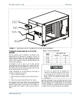
is recommended that a gas cock shutoff valve be installed in
the gas supply line outside the casing where it is readily
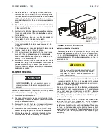
accessible, as close to the furnace as is practical, as shown
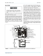
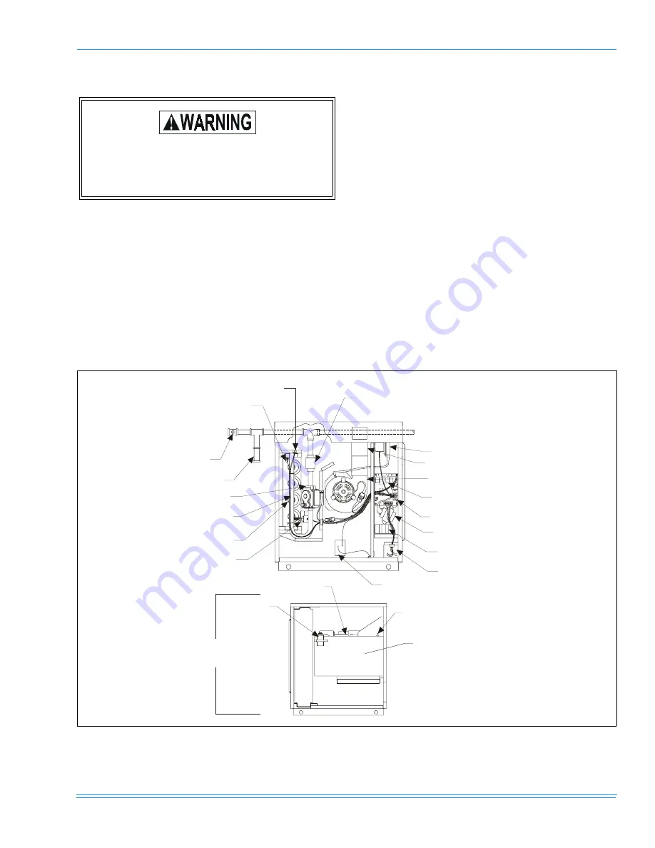
in Figure 3.
An 1/8 in. NPT (plugged) pressure tap for test gauge connec-
tion must be installed in the gas supply line immediately
upstream from the furnace if local authorities do not allow use
of the pressure tap in the gas valve for this purpose.
Install a dirt leg at the bottom of any vertical riser or drop, as
close to the furnace as possible, to collect moisture and for-
eign material. Install a ground joint union just ahead of the
gas control valve. A typical arrangement is shown in Figure 3.
Unless prohibited by local codes, it is permissible to use a
flexible corrugated metal gas connector for the last section of
gas piping connected to the furnace gas valve. If a flexible
connector is used, it must be certified to be in compliance
with ANSI Standard Z21.24 or, in Canada, with Standard
CAN1-6.10. When making the connection at the gas control
valve, use a wrench on the inlet side of the valve to prevent
any possible twisting of the valve body which could cause
damage and leaks. When making up pipe joints use pipe
thread compound which is resistant to natural and LP (pro-
pane) gases.
Following installation of the piping, first ensure that the gas
control knob on the gas valve is in the off position and then
pressurize the system with gas. Thoroughly check the piping
system for leaks.
Use only the type of gas for which the furnace is
equipped. Using the wrong gas could create a
hazard, resulting in damage, personal injury or
death.
FIGURE 3 :
OUTDOOR FURNACE: BURNER COMPARTMENT AND BLOWER ASSEMBLIES
ROLL-OUT SWITCH
FLAME
SENSOR
ALTERNATE
GAS PIPE
ROUTING
GAS SHUTOFF
DRIP LEG
GAS VALVE
BURNER
MANIFOLD
BURNERS
IGNITOR
LIMIT SWITCH
GROUND
JOINT UNION
PRESSURE SWITCH
PRIMARY
GAS PIPE
ROUTING
EXHAUST DUCT
INDUCER BLOWER
INTEGRATED
CONTROL BOARD
5 AMP. AUTOMATIC TYPE
CONTROL TRANSFORMER
LINE VOLTAGE
TERMINAL BLOCK
LOW VOLTAGE BOX
BLOWER MOTOR
CAPACITOR
LIMIT SWITCH
BLOWER
ASSEMBLY
BLOWER
ASSEMBLY


