650.67-N2V
035-15881-402 REV. A (1199)
8
Unitary Products Group
The maximum and minimum gas supply pressure required at
the inlet of the gas control valve is shown on the unit rating
plate. When the furnace is in operation, the inlet pressure
must be within the limits shown.
ELECTRICAL WIRING
All internal wiring has been made at the factory. Field wiring
requires only the connection of the line voltage supply wiring,
and low voltage thermostat wiring.
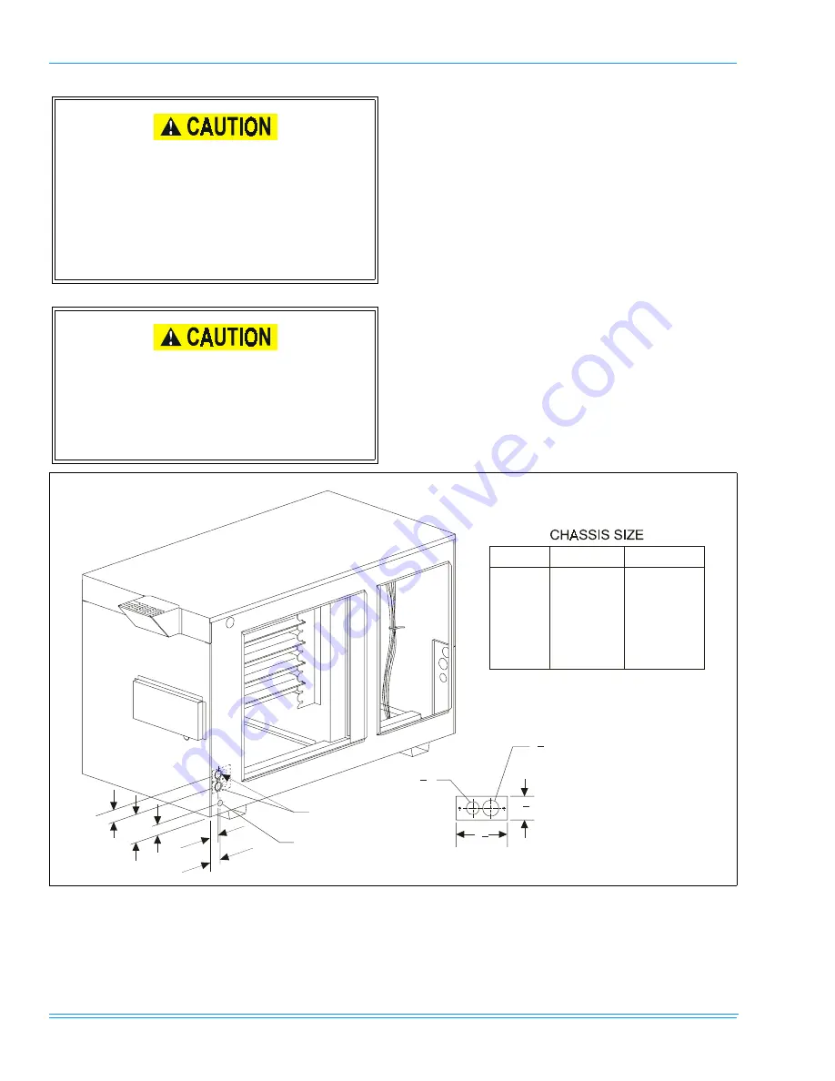
Line voltage supply wiring and control wiring may be brought
into the furnace through either side using the holes provided.
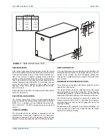
The furnace has been provided with two holes for line voltage
wiring, and one hole for thermostat wiring on each side. The
line voltage wiring plates may be removed, or removed and
reinstalled for different conduit sizes. (See Figures 4 and 5.)
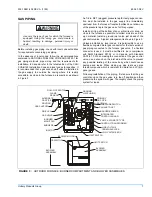
During pressure testing of the gas supply piping
system, observe the following to avoid fire, explo-
sion, asphyxiation, or damage to the appliance.
If test pressure is greater than 1/2 psig (3.48
kPa)(14" w.c.), the furnace and its individual shut-
off valve must be disconnected from the gas sup-
ply system.
Never use an open flame to check for leaks. Fire
or explosion could occur. Since some leak solu-
tions including soap and water may cause corro-
sion or stress cracking, the piping must be rinsed
with water after testing unless it has been deter-
mined that the leak solutions is noncorrosive.
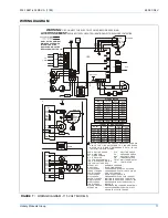
FIGURE 4 :
BASE MODEL FRONT VIEW
A
B
C
D
E
3
9
16
1
5
8
7
8
D
1
3
32
D
SMALL
LARGE
LETTER
A
B
C
D
E
2-1/8”
2-1/8”
2-1/4”
2-31/32”
1-9/16”
1-3/4”
2-1/8”
1-3/4”
4-1/8”
1-9/16”
LINE VOLTAGE
SUPPLY INLETS
7/8 DIA. LOW VOLTAGE
INLET HOLE


