035-15881-402 REV. A (1199)
650.67-N2V
Unitary Products Group
9
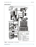
SERVICE WIRING
Field wiring connections should be made inside the control
box and a suitable strain relief should be used at the point the
wires exit the furnace casing. In order for the electrical con-
trols in the furnace to operate properly, correct electrical
polarity must be observed. Field wiring of the unit should con-
form to local codes or in the absence of local codes with the
National Electrical Code ANSI/NFPA 70. In Canada, field wir-
ing of the unit should conform to local codes or in the
absence of local codes with the Canadian Electrical Code,
Part I, CSA C22.1.
A separate fused circuit from the main electrical panel should
serve only the furnace.
ELECTRICAL GROUNDING
The furnace casing must have an uninterrupted electrical
ground in accordance with the National Electrical Code ANSI/
NFPA 70 or, in Canada, with the Canadian Electrical Code,
Part I, CSA C22.1. DO NOT use gas piping as an electrical
ground.
CONTROL WIRING
The thermostat should be installed in accordance with the
manufacturer's instructions, furnished with the thermostat,
and make connections to the unit as shown on the unit wiring
diagram. It is recommended that size 18 AWG wire be used.
HEAT ANTICIPATOR
If the wall thermostat has an adjustable heat anticipator, the
setting should be.48 amps. If any accessories are to be con-
nected to the furnace, the heat anticipator setting may
change. Use a suitable ammeter to measure the actual antic-
ipator current.
BLOWER MOTOR SPEED SELECTION
These furnaces are equipped with blowers which have multi-
speed direct drive motors.
The blower speed selected is dependent upon the design
and static pressure loss of the duct system. The duct system
external static pressure includes the combined total of the
supply and return ducts and any air conditioning coil if used.
The furnace must be adjusted to operate at or below the
maximum external static (in. W.C.) and within the air temper-
ature rise range as shown on the unit rating plate and in the
specification table.
Dependent upon the conditions in a particular installation, the
blower speeds may need to be changed to give the proper
operation on cooling or heating.
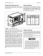
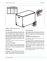
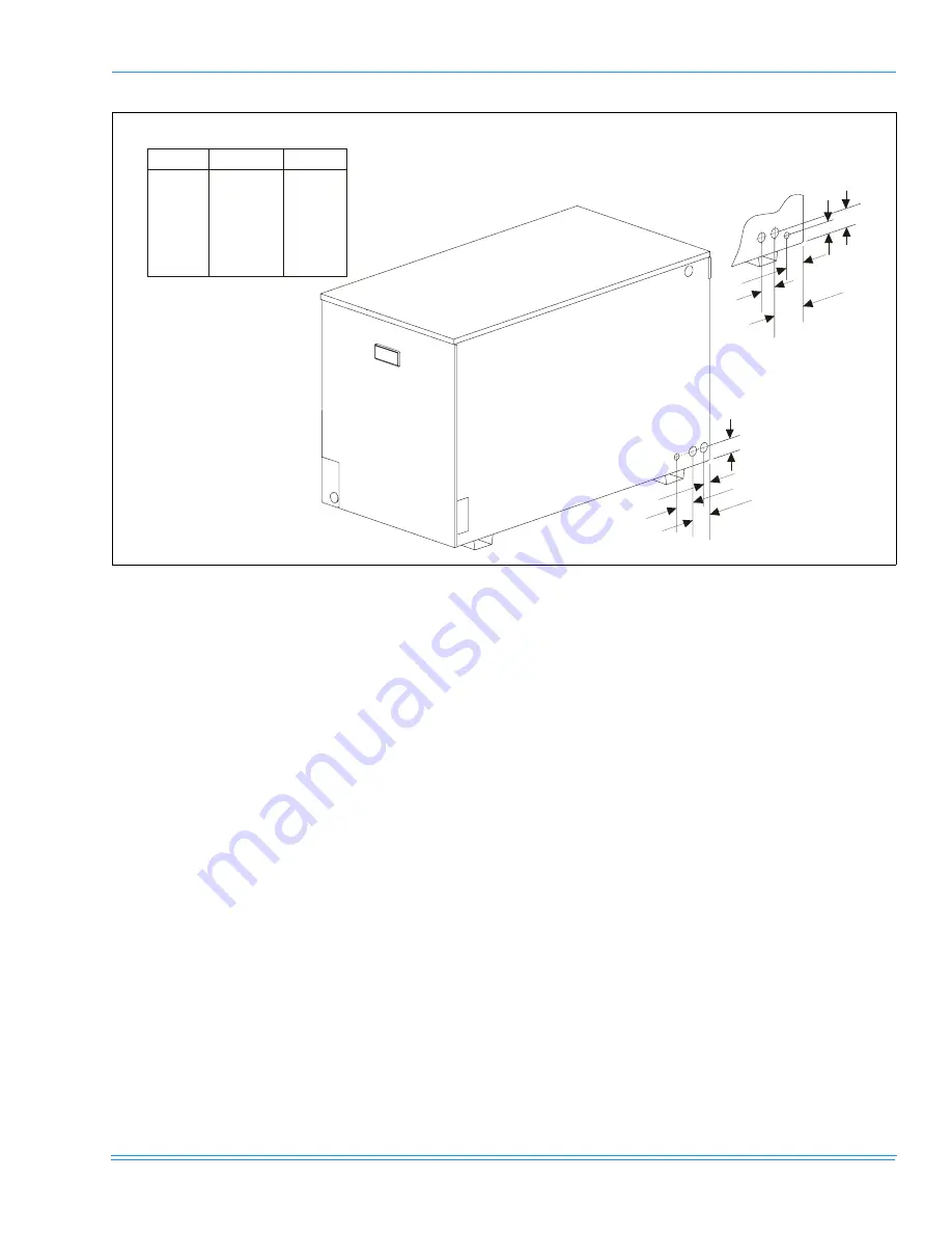
FIGURE 5 :
BASE MODEL REAR VIEW
F
G
H
J
F
H
G
J
K
CHASSIS SIZE
LETTER
SMALL
LARGE
F
G
H
J
K
1-3/4”
3-3/4”
2-3/16”
1-9/16”
2-3/8”
3-1/32”
3-1/4”
1-7/32”
2-3/32”
----


