


035-20464-002 Rev. A (1004)
Unitary Products Group
19
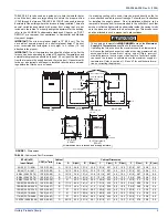
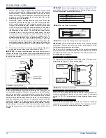
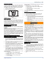
PRESSURE SWITCHES
This furnace is supplied with a pressure switch, which monitors the flow
through the combustion air/vent piping system. This switch de-ener-
gizes the ignition control module and the gas valve if any of the follow-
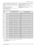
ing conditions are present. Refer to Figure 28 for tubing connections.
1.
Blockage of vent piping or terminal.
2.
Failure of combustion air blower motor.
LIMIT CONTROLS
There is a high temperature limit control located on the furnace vesti-
bule panel near the gas valve. This is an automatic reset control that
provides over temperature protection due to reduced airflow, that may
be caused by a dirty filter, or if the indoor fan motor should fail. The con-
trol module will lockout if the limit trips 3 consecutive times. Control will
reset & try ignition again after 1 hour.
SECTION IX: START-UP AND
ADJUSTMENTS
The initial start-up of the furnace requires the following additional
procedures:
IMPORTANT:
All electrical connections made in the field and in the fac-
tory should be checked for proper tightness.
When the gas supply is initially connected to the furnace, the gas piping
may be full of air. In order to purge this air, it is recommended that the
ground union be loosened until the odor of gas is detected. When gas is
detected, immediately retighten the union and check for leaks. Allow
five minutes for any gas to dissipate before continuing with the start-up
procedure. Be sure proper ventilation is available to dilute and carry
away any vented gas.
TOOLS AND INFORMATION THAT WILL BE
REQUIRED IN ORDER TO PROPERLY PERFORM THE
FURNACE STARTUP PROCEDURE.
1.
Call the local gas supplier to obtain heating value of the natural
gas. If you cannot obtain the heating valve of the gas from the gas
supplier, you may use a default value of 1030 BTU/SCF (38.8 MJ /
m³).
2.
You will need a thermometer or portable digital thermometer to
read the supply and return air temperatures.
3.
You will need a U-tube manometer or digital equipment that has
the ability to read pressures between 0 – 15” in.w.c (0 - 3.73 kPa)
in order to measure the gas line and the manifold pressures.
4.
You will need a 3/32” Allen wrench for the pressure port plugs in
the gas valve.
5.
You will need 2 pieces of 1/8” (0.3 cm) ID flexible tubing that is 12”
(30 cm) in length, 2 – pieces of 1/8” (0.3 cm) tubing that are 4”
(10.0 cm) in length, a 1/8” (0.3 cm) tee and a 1/8” (0.3 cm) adapter
to connect the U-tube manometer or the digital pressure measur-
ing equipment to the gas valve pressure ports.
There is an accessory kit (1PK0601) available from Source 1, which
has the following items:
•
1 - 12” (30 cm) length x 1/8” (0.3 cm) diameter tubing
•
2 – pieces of 4” (10 cm) length x 1/8” (0.3 cm) diameter tubing
•
1 - 5/16” (0.8 cm) tee
•
1 – 5/16” (0.8 cm) x 1/8” (3.175 mm) reducing coupling
•
1 – 1/8” (0.3 cm) adapter
There is a accessory kit (1PK0602) available from Source 1, which has
the following items:
•
12” (30 cm) length x 1/8” (0.3 cm) diameter tubing
•
2 – pieces of 4” (10 cm) length x 1/8” (0.3 cm) diameter tubing
•
1 - 5/16” (0.8 cm) tee
•
1 – 5/16” (0.8 cm) x 1/8” (0.3 cm) reducing coupling
•
1 – 1/8” (0.3 cm) adapter
•
1 - Dwyer – Manometer
These items are required in order to properly perform the required star-
tup procedure.
IGNITION SYSTEM SEQUENCE
1.
Turn the gas supply ON at external valve and main gas valve.
2.
Set the thermostat above room temperature to call for heat.
3.
System start-up will occur as follows:
a.
The induced draft blower motor will start and come up to
speed. Shortly after inducer start-up, the hot surface igniter
will glow for about 17 seconds.
b.
After this warm up, the ignition module will energize (open)
the main gas valve.
c.
After flame is established, the supply air blower will start in
about 30 seconds.
IMPORTANT:
Burner ignition may not be satisfactory on first startup
due to residual air in the gas line or until gas manifold pressure is
adjusted. The ignition control will make 3 attempts to light before lock-
ing out.
With furnace in operation, check all of the pipe joints, gas valve connec-
tions and manual valve connections for leakage using an approved gas
detector, a non-corrosive leak detection fluid, or other leak detection
methods. Take appropriate steps to stop any leak. If a leak persists,
replace the component.
The furnace and its equipment shutoff valve must be disconnected from
the gas supply piping system during any pressure testing of that system
at test pressures in excess of 1/2 PSI (3.45 kPa).
The furnace must be isolated from the gas supply piping system by
closing the equipment shutoff valve during any pressure testing of the
gas supply piping system.
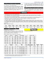
CALCULATING THE FURNACE INPUT
(NATURAL GAS)
NOTE:
Burner orifices are sized to provide proper input rate using natu-
ral gas with a heating value of 1050 BTU/Ft
3
(39.12 MJ/m
3
). If
the heating value of your gas is significantly different, it may be
necessary to replace the orifices.
NOTE:
Front door of burner box must be secured when checking gas
input.
1.
Turn off all other gas appliances connected to the gas meter.
2.
At the gas meter, measure the time (with a stop watch) it takes to
use 2 cubic ft. (0.0566 m
3
.) of gas.
3.
Calculate the furnace input by using one of the following equa-
tions.
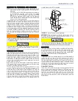
FIGURE 27:
Pressure Switch Tubing Routing
FIRE OR EXPLOSION HAZARD
Failure to follow the safety warnings exactly could result in serious
injury, death or property damage.
Never test for gas leaks with an open flame. Use a commercially
available soap solution made specifically for the detection of leaks
to check all connections. A fire or explosion may result causing
property damage, personal injury or loss of life.


