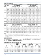

272317-UIM-A-0407
Unitary Products Group
21
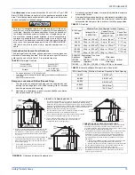
CONDENSATE DRAIN
The condensate trap must be filled with water before putting the furnace
into operation. Perform the following procedures only after the conden-
sate trap has been properly piped to a drain connection using the pro-
cedure in this instruction.
The recommended procedure is as follows:
1.
Disconnect the condensate drain hose from the induced draft
blower discharge.
2.
Elevate this hose and fill with water using a funnel.
3.
Replace the condensate drain hose and clamps.
IMPORTANT:
If this procedure is not followed, the unit may not properly
drain on initial start up.
CONDENSATE DRAIN TERMINATION
DO NOT terminate condensate drain in a chimney, or where the drain
line may freeze. The line must terminate at an inside drain to prevent
freezing of the condensate and possible property damage.
DO NOT trap the drain line at any other location than at the condensate
drain trap supplied with the furnace.
A condensate sump pump MUST be used if required by local codes, or
if no indoor floor drain is available. The condensate sump pump must
be approved for use with acidic condensate.
CONDENSATE DRAIN TRAP AND DRAIN FREEZE
PROTECTION
Special precautions MUST be made if installing furnace in an area
which may drop below freezing. This can cause improper operation or
damage to the equipment. If the furnace is installed in an area that has
the potential of freezing, the drain line and the drain trap must be pro-
tected. Use a 3 to 6 watt per foot at 115 vac, 40º F (4.4° C) self-regulat-
ing, shielded and waterproof heat tape. Wrap the drain trap and the
drain line with the heat tape and secure with ties. Follow the heat tape
manufacturer's recommendations.
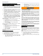
SECTION VIII: SAFETY CONTROLS
CONTROL CIRCUIT FUSE
A 3-amp fuse is provided on the control circuit board to protect the 24-
volt transformer from overload caused by control circuit wiring errors.
This is an ATO 3, automotive type fuse and is located on the control
board.
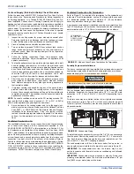
BLOWER DOOR SAFETY SWITCH
This unit is equipped with an electrical interlock switch mounted in the
blower compartment. This switch interrupts all power at the unit when
the panel covering the blower compartment is removed.
Electrical supply to this unit is dependent upon the panel that covers the
blower compartment being in place and properly positioned.
ROLLOUT SWITCH CONTROLS
These controls are mounted on the burner box assembly. If the temper-
ature in the burner box exceeds its set point, the ignition control and the
gas valve are de-energized. The operation of this control indicates a
malfunction in the combustion air blower, heat exchanger or a blocked
vent pipe connection. Corrective action is required. These are manual
reset controls that must be reset before operation can continue.
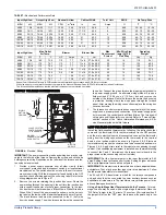
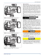
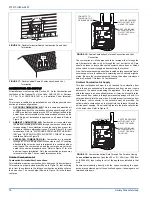
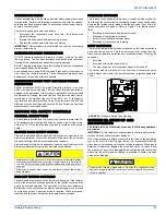
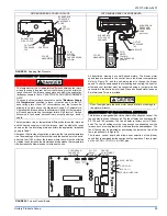
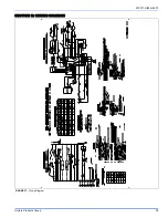
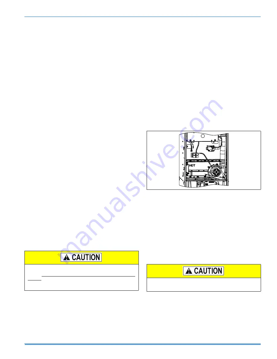
PRESSURE SWITCHES
This furnace is supplied with two pressure switches which monitor the
flow through the combustion air/vent piping system. These switches de-
energize the ignition control module and the gas valve if any of the fol-
lowing conditions are present. Refer to Figure 23 for tubing connec-
tions.
1.
Blockage of combustion air piping or terminal.
2.
Blockage of vent piping or terminal.
3.
Failure of combustion air blower motor.
4.
Blockage of condensate drain piping.
LIMIT CONTROLS
There is high temperature limit control located on the furnace vestibule
panel near the gas valve. This is an automatic reset control that pro-
vides over-temperature protection due to reduced airflow. This may be
caused by
1.
dirty filter,
2.
if the indoor fan motor should fail, or
3.
Too many supply or return registers closed or blocked off.
The control module will lockout if the limit trips 5 consecutive times
within a single call for heat. Control will reset and try ignition again after
1 hour.
SECTION IX: START-UP AND
ADJUSTMENTS
The initial start-up of the furnace requires the following additional
procedures:
IMPORTANT:
All electrical connections made in the field and in the fac-
tory should be checked for proper tightness.
When the gas supply is initially connected to the furnace, the gas piping
may be full of air. In order to purge this air, it is recommended that the
ground union be loosened until the odor of gas is detected. When gas is
detected, immediately retighten the union and check for leaks. Allow
five minutes for any gas to dissipate before continuing with the start-up
procedure. Be sure proper ventilation is available to dilute and carry
away any vented gas.
Main power to the unit must still be interrupted at the main power
disconnect switch before any service or repair work is to be done to
the unit. Do not rely upon the interlock switch as a main power dis-
connect.
Blower and burner must never be operated without the blower
panel in place.
FIGURE 23:
Pressure Switch Tube Routing
Perform the following procedures only after the condensate trap
has been properly piped to a drain connection using the procedure
in this instruction.


