272317-UIM-A-0407
Unitary Products Group
9
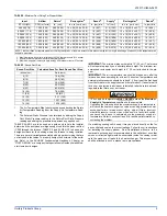
Annual Fuel Utilization Efficiency (AFUE) numbers are determined in accordance with DOE Test procedures.
Wire size and over current protection must comply with the National Electrical Code (NFPA-70-latest edition) and all local codes.
The furnace shall be installed so that the electrical components are protected from water.
SUPPLY VOLTAGE CONNECTIONS
IMPORTANT:
The power connection leads and wiring box may be relo-
cated to the left side of the furnace. Remove the screws and cut wire tie
holding excess wiring. Reposition on the left side of the furnace and fas-
ten using holes provided.
1.
Provide a power supply separate from all other circuits. Install
overcurrent protection and disconnect switch per local/national
electrical codes. The switch should be close to the unit for conve-
nience in servicing. With the disconnect or fused switch in the OFF
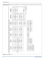
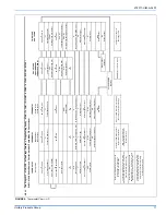
position, check all wiring against the unit wiring label. Refer to the
wiring diagram shown in Figure 27.
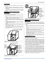
2.
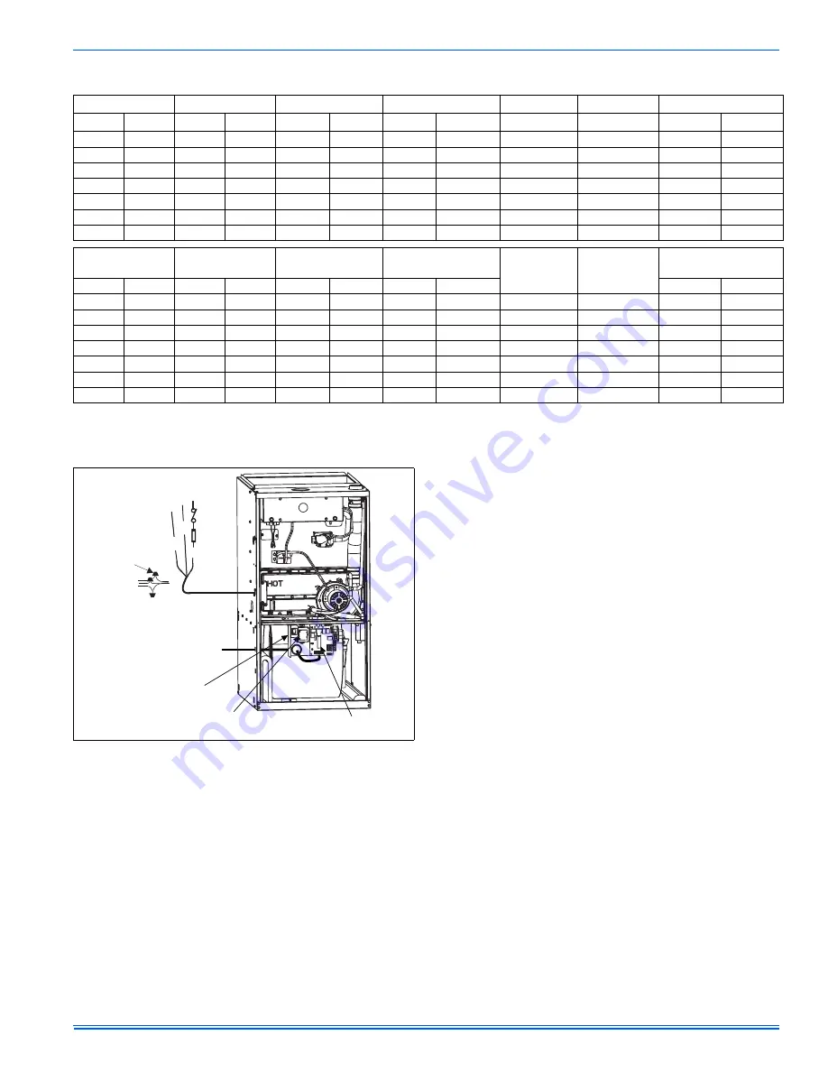
Remove the screws retaining the junction box cover. Route the
power wiring through the opening in the unit into the junction box
with a conduit connector or other proper connection. In the junc-
tion box there will be three wires, a Black Wire, a White Wire and a
Green Wire. Connect the power supply as shown on the unit-wir-
ing label on the inside of the blower compartment door or Figure 4.
The black furnace lead must be connected to the L1 (hot) wire
from the power supply. The white furnace lead must be connected
to neutral. Connect the green furnace lead (equipment ground) to
the power supply ground. An alternate wiring method is to use a
field provided 2” (5.08 cm) x 4” (10.2 cm) box and cover on the
outside of the furnace. Route the furnace leads into the box using
a protective bushing where the wires pass through the furnace
panel. After making the wiring connections replace the wiring box
cover and screws.
3.
The furnace's control system requires correct polarity of the power
supply and a proper ground connection. If the power supply polar-
ity is reversed, the control board will flash 9 times. The furnace will
not operate until the polarity is corrected. Refer to “Furnace Diag-
nostics” section of the “User’s Information, Maintenance, & Ser-
vice Manual provided with this furnace.
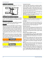
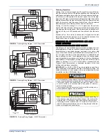
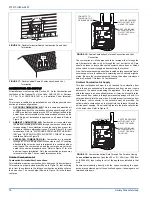
LOW VOLTAGE CONTROL WIRING CONNECTIONS
Install the field-supplied thermostat by following the instructions that
come with the thermostat. With the thermostat set in the OFF position
and the main electrical source disconnected, connect the thermostat
wiring from the wiring connections on the thermostat to the terminal
board on the ignition module, as shown in Figures 5 & 6. Electronic
thermostats may require the common wire to be connected as shown in
Figures 5 & 6. Apply strain relief to thermostat wires passing through
cabinet. If air conditioning equipment is installed, use thermostat wiring
to connect the Y and C terminals on the furnace control board to the
proper wires on the condensing unit (unit outside).
IMPORTANT:
Set the heat anticipator in the room thermostat to 0.45
amps. Setting it lower will cause short cycles. Setting it higher will cause
the room temperature to exceed the set points.
IMPORTANT:
Some electronic thermostats do not have adjustable heat
anticipators. They may have other type cycle rate adjustments. Follow
the thermostat manufacturer's instructions.
The 24-volt, 40 VA transformer is sized for the furnace components
only, and should not be connected to power auxiliary devices such as
humidifiers, air cleaners, etc. The transformer may provide power for an
air conditioning unit contactor.
Using a Single-Stage Heat Thermostat with the Furnace
- This two-
stage furnace may be used with a single-stage thermostat. Place the
“W2 Delay” jumper in the 10 minute, 15 minute or 20 minute position. If
the jumper is left on the “OFF” pins, the furnace will operate only in low
fire.
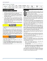
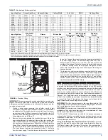
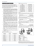
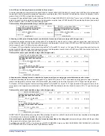
TABLE 7:
Electrical and Performance Data
Input High/Low
Output High/Low
Nominal Airflow
Cabinet Width
Total Unit
AFUE
Air Temp. Rise
MBH
kW
MBH
kW
CFM
m
3
/min
In.
cm
Amps
%
°F
°C
40/26
12/8
38/24
11/7
1200
34.0
14-1/2
36.8
9
94.0
35 - 65
19 - 36
60/39
18/11
56/36
16/11
1200
34.0
17-1/2
44.4
9
93.2
40 - 70
22 - 39
80/52
23/15
75/49
22/14
1200
34.0
17-1/2
44.4
9
92.5
45 - 75
25 - 42
80/52
23/15
75/49
22/14
1600
45.3
21
53.3
12
92.8
45 - 75
25 - 42
100/65
29/19
93/60
27/18
1600
45.3
21
53.3
12
92.5
45 - 75
25 - 42
100/65
29/19
93/60
27/18
2000
56.6
21
53.3
14
92.8
45 - 75
25 - 42
120/78
35/23
112/73
33/21
2000
56.6
24-1/2
62.2
14
93.2
40 - 70
22 - 39
Input High/Low
Max. Outlet
Air Temp.
Blower
Blower Size
Max.
Over-current
Protect
Min. Wire Size
(awg) @ 75 ft.
One Way
Operating
Weight
MBH
kW
°F
°C
HP
Amps
In.
cm
Lbs.
Kg
40/26
12/8
165
73.9
1/2
7.7
11 x 8
27.9 x 20.3
20
14
119
54.1
60/39
18/11
170
76.7
1/2
7.7
11 x 8
27.9 x 20.3
20
14
133
60.5
80/52
23/15
175
79.4
1/2
7.7
11 x 8
27.9 x 20.3
20
14
140
63.6
80/52
23/15
175
79.4
3/4
10.2
11 x 10
27.9 x 25.4
20
14
155
70.5
100/65
29/19
175
79.4
3/4
10.2
11 x 10
27.9 x 25.4
20
14
160
72.7
100/65
29/19
175
79.4
1
12.8
11 x 11
27.9 x 27.9
20
12
162
73.6
120/78
35/23
170
76.7
1
12.8
11 x 11
27.9 x 27.9
20
12
178
80.9
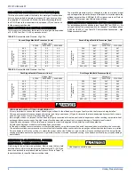
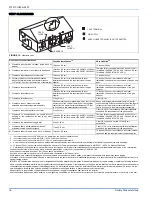
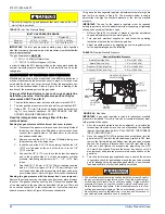
FIGURE 4:
Electrical Wiring
N
GND
L1
HOT
WHT
GRN
BLK
BLK/BLK
WHT/WHT
GRN/GRN
CLASS 2 SYSTEM
CONTROL WIRING
TO THERMOSTAT
BLOWER
COMPARTMENT
DOOR SWITCH
TRANSFORMER
IGNITION
MODULE


