268894-UIM-A-0407
Unitary Products Group
7
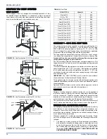
SUSPENDED FURNACE / CRAWL SPACE
INSTALLATION
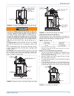
The furnace can be hung from floor joists or installed on suitable blocks
or pad. Blocks or pad installations shall provide adequate height to
ensure the unit will not be subject to water damage. Units may also be
suspended from rafters or floor joists using rods, pipe angle supports or
straps. Angle supports should be placed at the supply air end and near
the blower deck. Do not support at return air end of unit. All four sus-
pension points must be level to ensure quiet furnace operation. When
suspending the furnace use a secure platform constructed of plywood
or other building material secured to the floor joists. Refer to Figure 3
for typical crawl space installation.
In any application where temperatures below freezing are possible,
see “INSTALLATION IN FREEZING TEMPERATURES” in SEC-
TION I
FIGURE 3:
Typical Suspended Furnace / Crawl Space Installation
ANGLE IRON
BRACKET
6” MIN. BETWEEN
ROD & FRONT OF FURNACE
1” MAX. BETWEEN
ROD & BACK OF FURNACE
SUPPORT
BRACKET
FIGURE 4:
Dimensions
FRONT
LEFT SIDE
RIGHT SIDE
FRONT
FRONT
BOTTOM IMAGE
TOP IMAGE
A
B
40
3/4
20
31-1/8
5-3/4
2-1/2
28-1/2
1-1/8
7-3/8
A
C
20
1-1/4
T’STAT WIRING
7/8” K.O.
GAS INLET
1-1/4” X 2-1/2”
ALT. GAS INLET
1-1/4” X 2-1/2”
(VENT CONNECTION)
5
1-7/8
20
B
D
3-3/4
4” Diameter
4” Diameter
TABLE 4:
Cabinet and Duct Dimensions
BTUH (kW)
Input
Airflow
CFM (m
3
/min)
Cabinet
Size
Cabinet Dimension
A
A (cm)
B
B (cm)
C
C (cm)
D
D(cm)
40 (11.7)
1200 (34.0)
A
14 1/2
36.8
13 1/4
33.6
12
30.5
10 3/8
26.4
60 (17.6)
1200 (34.0)
A
14 1/2
36.8
13 1/4
33.6
12
30.5
10 3/8
26.4
80 (23.4)
1200 (34.0)
A
14 1/2
36.8
13 1/4
33.6
12
30.5
10 3/8
26.4
80 (23.2)
1600 (45.3)
B
17 1/2
44.4
16 1/4
41.3
15
38.1
11-3/4
29.8
80 (23.2)
1600 (45.3)
C
21
53.3
19 3/4
50.2
18-1/2
47.0
13 1/2
34.3
100 (29.3)
1200 (34.0)
B
17 1/2
44.4
16 1/4
41.3
15
38.1
11 3/4
29.8
100 (29.3)
1600 (45.3)
C
21
53.3
19 3/4
50.2
18-1/2
38.1
13 1/2
34.3
100 (29.3)
2000 (56.6)
C
21
53.3
19 3/4
50.2
18-1/2
47.0
13 1/2
34.3
115 (33.7)
1600 (45.3)
C
21
53.3
19 3/4
50.2
18-1/2
47.0
13 1/2
34.3
115 (33.7)
2000 (56.6)
C
21
53.3
19 3/4
50.2
18-1/2
47.0
13 1/2
34.3
130 (38.1)
2000 (56.6)
D
24 1/2
62.2
23 1/4
59.1
22
55.9
15 1/4
38.7

