035-18575-001-A-1102
Unitary Products Group
7
1.
The condensing unit is designed for outdoor instal-
lation only.
2.
The condenser fans are the propeller type and are
not suitable for use with ductwork in the condenser
air stream.
3.
The condensing unit and the evaporator should be
positioned to minimize the number of bends in the
refrigerant piping.
4.
The condensing unit should be as close to the
evaporator as practical.
5.
The condensing unit should not be installed where
normal operating sounds may be objectionable.
6.
The evaporator should be located within the build-
ing, either outside or inside the conditioned space.
ROOFTOP LOCATIONS
Be careful not to damage the roof. Consult the building
contractor or architect if the roof is bonded. Choose a
location with adequate structural strength to support
the unit.
The condensing unit must be mounted on level sup-
ports. The supports can be channel iron beams or
wooden beams treated to reduce deterioration.
Minimums of two (2) beams are required to support
each unit. The beams should: (1) be positioned per-
pendicular to the roof joists. (2) Extend beyond the
dimensions of the section to distribute the load on the
roof. (3) Be capable of adequately supporting the con-
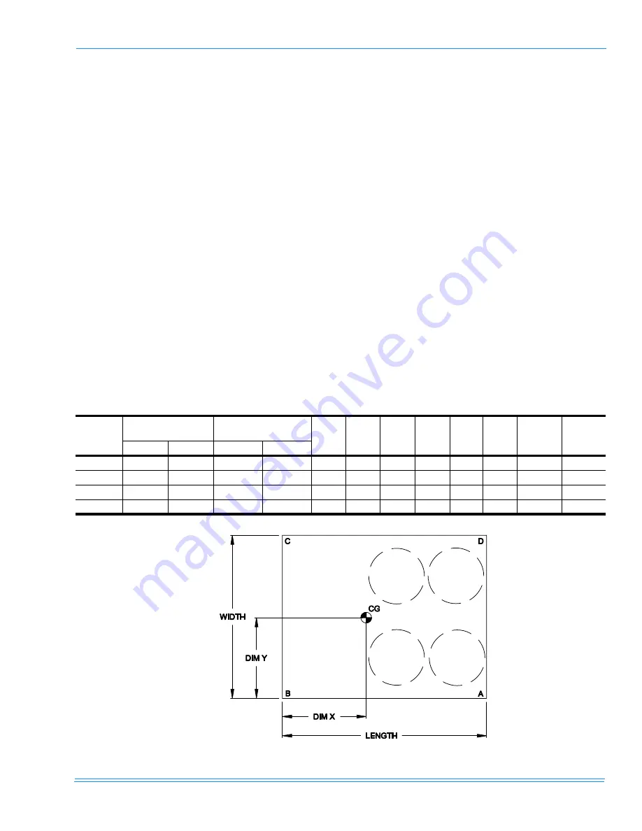
centrated loads at the corners. See Figure 1.
These beams can usually be set directly on the roof.
Flashing is not required.
NOTE: On bonded roofs, check for special installation
requirements.
GROUND LEVEL LOCATIONS
It is important that the units be installed on a substan-
tial base that will not settle, causing strain on the refrig-
erant lines and possible leaks. A one-piece concrete
slab with footers that extend below the frost line is rec-
ommended. The slab should not be tied to the building
foundation, as noise will telegraph.
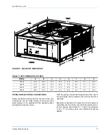
TABLE 3: CORNER WEIGHTS & CENTER OF GRAVITY (INCHES)
Unit Model
Unit Weight (Lbs.)
Unit Dimensions
(Inches)
A
B
C
D
Dim X
Dim Y
Weight
A to D
Weight
B to C
Shipping
Operation
Length
Width
HA300
1608
1658
110.46
88.46
337
412
472
386
49.7
47.7
723.5
884.5
HB360
1730
1790
110.46
88.46
363
531
497
339
44.8
42.8
701.6
1028.4
HB480
1961
2037
128.46
88.46
393
598
585
385
51.0
43.8
778.5
1182.5
HB600
2470
2563
128.46
88.46
470
757
767
476
49.2
44.5
946.0
1524.0
FIGURE 1 - CORNER WEIGHTS & CENTER OF GRAVITY


