035-18575-001-A-1102
8
Unitary Products Group
Concrete piers can also support ground level units.
These piers should (1) extend below the frost line, (2)
be located under each of the section's four corners,
and (3) be sized to carry the load of the corner it sup-
ports.
On either rooftop or ground level installations, rubber
padding can be applied under the unit to lessen any
transmission of vibration.
Holes are provided in the base rails for bolting the unit
to its foundation.
For ground level installations, precautions should be
taken to protect the unit from tampering and unautho-
rized persons from injury. Screws on access panels will
prevent casual tampering. Further safety precautions
such as a fenced enclosure or locking devices on the
panels may be advisable. Check local authorities for
safety regulations.
CLEARANCES
The units must be installed with sufficient clearance for
air to enter the condenser coil, for air discharge and for
servicing access. See Table 4 for clearances.
NOTE: Additional clearance is required to remove the
compressors out the side of the unit, unless a
means is available to lift the compressor out
through the top of the unit.
RIGGING
Exercise care when moving the unit. Do not remove
any crating until the unit is near the place of installation.
When preparing to move the unit, always determine the
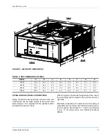
center of gravity (see Table 3 and Figure 1) of the unit
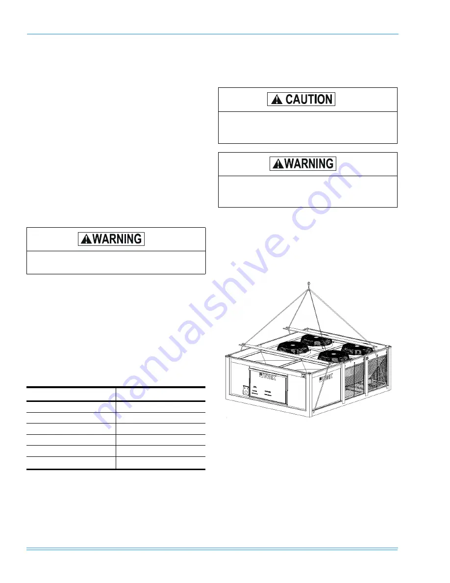
in order to equally distribute the weight. Slings con-
nected to the compressor end of a unit will usually have
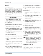
to be made shorter, so the unit will lift evenly (see
Figure 2).
Rig units by attaching chain or cable hooks to the holes
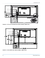
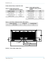
provided on the base rail. See Figure 6 for details on
rigging holes.
The length of the spreader bars must exceed the width
of the unit. Refer to Table 3 for unit weights.
Do not permit overhanging structures or shrubs
to obstruct condenser air discharge.
TABLE 4: MINIMUM CLEARANCES
Clearance Description
Distance in Inches
Overhead (Top)
120
Front (Access Cover)
36
Rear (piping connections)
36
Left Side
30
Right Side
30
Bottom
*
*.
In all installations where snow accumulates and winter
operation is expected, additional height must be provided
to insure normal condenser airflow.
0
Spreaders, longer than the largest dimension
across the unit must be used across the top of
the unit.
Before lifting a unit, make sure that its weight is
distributed equally on the cables so that it will
lift evenly.
FIGURE 2 - TYPICAL RIGGING


