278806-BIM-A-1106
Unitary Products Group
23
SAFETY CONTROLS
The Simplicity™ control board incorporates features to
monitor safety circuits as well as minimize compressor
wear and damage. An anti-short cycle delay (ASCD) is
utilized to prevent operation of a compressor too soon
after its previous run. Additionally, a minimum run time
is imposed anytime a compressor is energized to allow
proper oil return to the compressor. The ASCD is initi-
ated on unit start-up and on any compressor reset or
lockout.
The Simplicity™ control board monitors the following
inputs for each cooling system:
•
A high-pressure switch is factory installed to pro-
tect against excessive discharge pressure due to a
blocked condenser coil or a condenser fan motor
failure. During cooling operation, if a high-pressure
limit switch opens, the Simplicity™ control board
will de-energize the associated compressors and
initiate the 5-minute ASCD. If the call for cool is still
present at the end of the ASCD, the control board
will re-energize the halted compressor.
•
If a high-pressure switch opens three times within
two hours of operation, the Simplicity™ control
board will lockout the associated system compres-
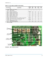
sors and will flash an error code (see Table 13).
•
A low-pressure switch to protect the unit against
excessively low suction pressure is standard on all
condensing units.
If the low-pressure switch opens during normal opera-
tion, the Simplicity™ control board will de-energize the
compressor, initiate the ASCD, and shut down the con-
denser fans.
On startup, if the low-pressure switch opens, the Sim-
plicity™ control board will monitor the low-pressure
switch to make sure it closes within one minute. If it
fails to close, the unit will shut down the associated
compressor and begin an ASCD. If the call for cool is
still present at the end of the anti-short cycle time
delay, the control board will re-energize the halted
compressor.
If a low-pressure switch opens three times within one
hour of operation, the Simplicity™ control board will
lock-out the associated compressor and flash an error
code (see Table 13).
An ambient air switch will lock out mechanical cooling
at 40
°
F. In order to operate the unit in ambient temper-
atures below 40
°
F, the optional low ambient kit must be
field installed which will allow the unit to operate during
conditions down to 0
°
F.
The refrigerant systems are independently monitored
and controlled. On any fault, only the associated sys-
tem will be affected by any safety/preventive action.
The other refrigerant system will continue to operate
unless it is affected by the fault as well.
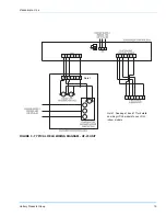
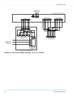
PUMP OUT
The pump out function is a standard feature on the 25
to 50 ton systems. The pump out circuit is activated
each time the first and third compressor stage is called
for by the thermostat. As such, it’s a “Pump Out On
Start Up” design. A normally closed solenoid valve
(POS1, 2, 3 or 4) is placed in the liquid line, just prior to
expansion valve.
When cooling is not being called for by the thermostat,
the pump out solenoid (POS) is not energized, so it’s in
the closed position. When the Simplicity™ control
receives a call for cooling, it energizes a compressor.
With the POS being closed, it causes the pressure on
the low side of the system to begin falling.
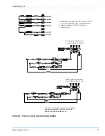
When the low pressure switch (LPS) opens, the control
board energizes its on-board pump out relay, providing
a 24vac output to an external relay used to energized
the pump out solenoid. The refrigeration circuit being
controlled is not in normal operating mode.
If the low pressure switch is already open on a call for
cooling, the pump out relay is energized immediately. If
the LPS does not open after 5 minutes, the pump out
relay is energized.
CONTINUOUS BLOWER
By setting the room thermostat to “ON,” the supply air
blower will operate continuously.
INTERMITTENT BLOWER
With the room thermostat fan switch set to “AUTO” and
the system switch set to either the “AUTO” or “HEAT”
settings, the blower is energized whenever a cooling or
heating operation is requested. The blower is ener-
gized after any specified delay associated with the
operation.
When energized, the indoor blower has a minimum run
time of 30 seconds. Additionally, the indoor blower has
a delay of 10 seconds between operations.


