278806-BIM-A-1106
Unitary Products Group
9
NOTE:
If planning to handle the 25-50 ton split with a
fork truck, 1WS0407 skid for HF-25/HL-30 and
1WS0408 skid for HL-40/-50 units will be
required.
POWER WIRING
Check the available power and the unit nameplate for
like voltage. Run the necessary number of properly
sized wires to the unit. Provide a disconnect switch (if
not included with the unit) and fusing as required.
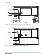
Route the conduit through the large knockout located
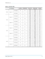
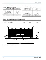
on the front of the electrical box. See Table 5 for Elec-
trical Data.
The disconnect switch may be bolted to the side of the
unit but not to any of the removable panels; this would
interfere with access to the unit. Make sure that no
refrigerant lines will be punctured when mounting the
disconnect switch, and note that it must be suitable for
outdoor installation.
START-UP
PHASING
The units are properly phased at the factory. Check for
proper compressor rotation. If the fans or compressors
rotate in the wrong direction at start-up, the electrical
connection to the unit is misphased. Change the
incoming line connection phasing to obtain proper rota-
tion. (Scroll compressors operate in only one direction.
If the scroll is drawing low amperage, has similar suc-
tion and discharge pressures, or producing a high
noise level, the scroll is misphased.)
CONTROL WIRING
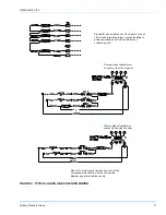
Route the necessary low voltage control wires from the
Simplicity™ control board to the thermostat and also
from the low voltage condensing section control box or
the terminal block inside the evaporator unit and to the
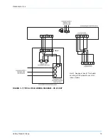
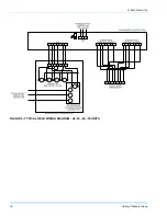
evaporator fan motor controller. Refer to Figures 3 and
4 for field wiring diagrams. A terminal block is provided
in the evaporator control box to accommodate the wir-
ing from the evaporator solenoid valves.
COMPRESSOR CRANKCASE HEATERS
The compressors are equipped with crankcase heaters
to prevent the migration of refrigerant to the compres-
sors. The heaters are energized only when the unit is
not running.
If the main switch is disconnected for long periods of
shut down, do not attempt to start the unit for 8 hours
after the switch has been re-connected. This will allow
sufficient time for all liquid refrigerant to be driven out of
the compressor.
If handling a unit equipped with a 1WS skid,
length of forks must be a minimum of 96”. Fork
lengths less than 96” will not span the required
width of the skid and can cause damage to the
unit’s base rails or condenser coils.
All power and control wiring must be in accor-
dance with National and Local electrical codes.
Scroll compressors require proper rotation to
operate correctly. Units are properly phased at
the factory. Do not change the internal wiring to
make the blower condenser fans or compres-
sor rotate correctly.


