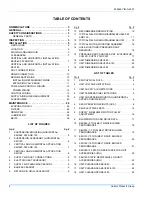


CONTENTS
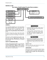
GENERAL. . . . . . . . . . . . . . . . . . . . . . . . . . . . . . . . . . . . 3
SAFETY CONSIDERATIONS . . . . . . . . . . . . . . . . . . . . 3
INSPECTION . . . . . . . . . . . . . . . . . . . . . . . . . . . . . . . . . 3
INSTALLATION . . . . . . . . . . . . . . . . . . . . . . . . . . . . . . . 5
MAINTENANCE . . . . . . . . . . . . . . . . . . . . . . . . . . . . . . 26
See the following page for a complete Table of Contents.
NOTES, CAUTIONS AND WARNINGS
Installer should pay particular attention to the words:
NOTE
,
CAUTION
, and
WARNING
. Notes are intended to
clarify or make the installation easier. Cautions are given
to prevent equipment damage. Warnings are given to
alert installer that personal injury and/or equipment dam-
age may result if installation procedure is not handled
properly.
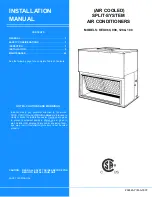
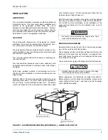
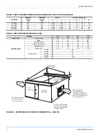
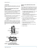
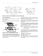
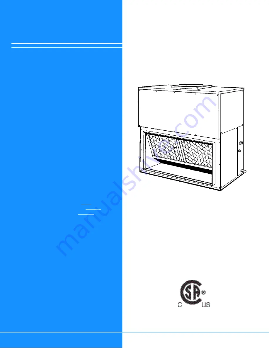
INSTALLATION
MANUAL
CAUTION:
READ ALL SAFETY GUIDES BEFORE YOU
BEGIN TO INSTALL YOUR UNIT.
SAVE THIS MANUAL
(AIR COOLED)
SPLIT-SYSTEM
AIR CONDITIONERS
MODELS: KEU060, 090, 120 & 180
292426-YIM-A-0307


