


292426-YIM-A-0307
8
Unitary Products Group
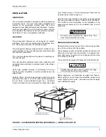
DUCT CONNECTIONS
Design and install all ducts in accordance with all national
and/or local codes.
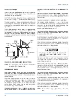
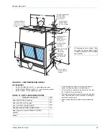
Refer to Figure 5 for suggested method of connecting supply
air ductwork.
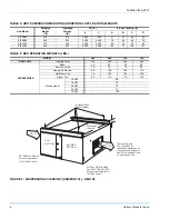
Ducts should be sized no smaller than the duct flanges on the
unit or the electric heater (if used). Refer to the unit dimen-
sion details (Figure 16) and the heater detail (Figure 6) for
these sizes. Refer to Form 131002 for installation instructions
on the electric heater.
Use flexible fiber glass or plastic cloth collars or other non-
flammable material at the unit duct connections to minimize
the transmission of noise and vibration.
Insulate all ductwork running through unconditioned areas to
prevent moisture condensation and to provide more econom-
ical operation.
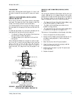
The return air duct flange is factory-mounted on the front of
the unit, but it can be reversed with the solid bottom panel for
horizontal applications. When the return air grill is used, the
duct connection frame is not used.
NOTE:
If return air duct is not used, applicable installation
codes may limit the unit to installation only in a sin-
gle story residence.
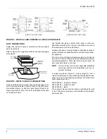
A supply air plenum (Figure 7), a base (Figure 8), and a
return air grill (Figure 9) are available as field-installed acces-
sories, and one of the following respective instruction forms
will be packed with each.
035-16650-001 - Supply Air Plenum
035-16621-001 - Return Air Grill
035-16632-001 - Base
The supply air plenum and the return air grill should be used
in lieu of ductwork only when a free blow/free return applica-
tion is practical.
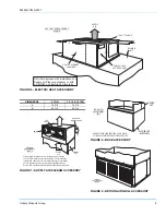
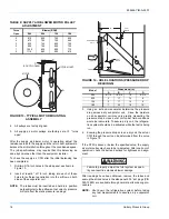
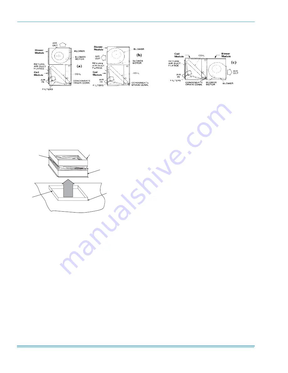
FIGURE 4 - VERTICAL AND HORIZONTAL APPLICATION KEU180
9(57,&$/326,7,21
+25,=217$/326,7,21
FIGURE 5 - SUPPLY AIR DUCT CONNECTIONS
AIR
OUT
NON-FLAMMABLE
COLLAR
FLANGEDDUCT
CONNECTION
(FIELD
FABRICATED)
DUCT
SUPPLYAIR
DUCTFLANGE
BLOWERGASKET
(BYINSTALLER)


