INSTALLATION
MANUAL
CAUTION:
READ ALL SAFETY GUIDES BEFORE YOU
START TO INSTALL UNIT.
SAVE THIS MANUAL
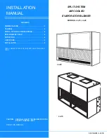
SPLIT-SYSTEM
AIR COOLED
EVAPORATOR BLOWER
MODELS: LL-15, LL-20
66339-BIM-C-0206
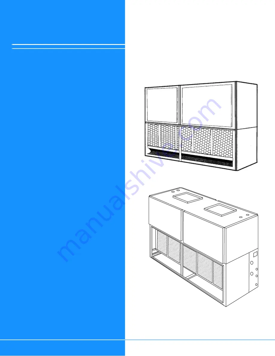
LL-20
LL-15
CONTENTS
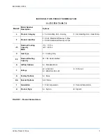
NOMENCLATURE . . . . . . . . . . . . . . . . . . . . . . . . . . . . . .3
GENERAL . . . . . . . . . . . . . . . . . . . . . . . . . . . . . . . . . . . .4
NOTES, CAUTIONS AND WARNINGS. . . . . . . . . . . . . .4
REPLACEMENT PARTS . . . . . . . . . . . . . . . . . . . . . . . . .4
INSPECTION . . . . . . . . . . . . . . . . . . . . . . . . . . . . . . . . . .4
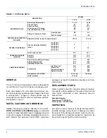
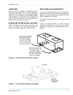
LIMITATIONS. . . . . . . . . . . . . . . . . . . . . . . . . . . . . . . . . .5
INSTALLATION . . . . . . . . . . . . . . . . . . . . . . . . . . . . . . . .9
FOR A COMPLETE TABLE OF CONTENTS, SEE FOLLOWING
PAGE.


