66339-BIM-C-0206
Unitary Products Group
11
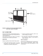
RETURN AIR DUCT ANGLES
Return air duct angles are shipped turned in. They are
intended to be unscrewed and turned for connection of
ductwork.
DRAIN CONNECTIONS
All drain lines MUST be trapped and located so they
will not be exposed to freezing temperatures.
The LL-20 evaporator blower has 7/8” OD steel con-
densate stub at each end of a single drain pan. Both
ends are closed with plastic caps. A plastic ell (field
supplied) can be used. Attach the ell to the desired end
and run a full size 7/8” drain line to the nearest drain
facility. Seal the cap at the unused end with suitable
mastic. The LL-15 evaporator has one 7/8” OD drain
connection through the right side of the cabinet.
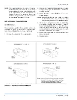
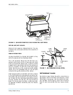
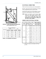
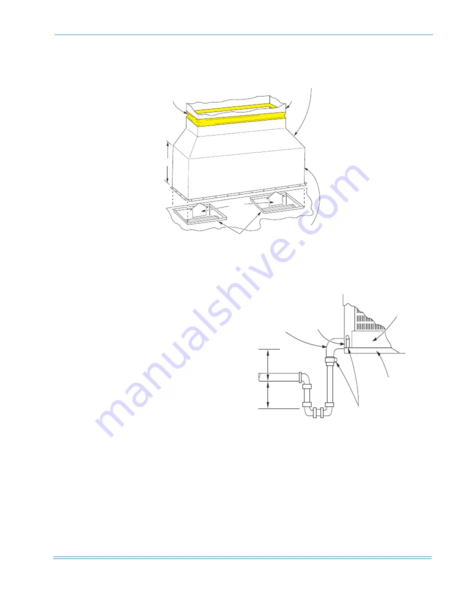
Drain piping should be constructed as shown in figure
9. The 5-inch dimension is intended to exceed the neg-
ative static pressure developed by the supply air blow-
ers. If it does not, the condensate will not drain properly
and may overflow the drain pan. The trap must be at
least 2 1/2 inches deep to maintain a water seal under
all operating conditions, especially when the blowers
are starting.
REFRIGERANT MAINS
Hard drawn copper tubing should be used where no
appreciable amount of bending around pipes or other
obstructions is necessary. Use long radius ells wher-
ever possible. If soft copper is used, care should be
taken to avoid sharp bends that may cause a restric-
tion.
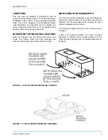
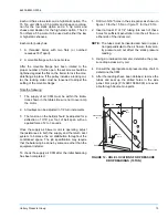
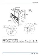
FIGURE 10 - SUGGESTED METHOD FOR CONNECTING DUCTWORK
24"
AIR
OUTLET
BLOWER
GASKETS
(BY INSTALLER)
FLANGED DUCT
CONNECTION
(FIELD
FABRICATED)
NON-FLAMMABLE
COLLAR
DUCT
TRANSITION
DUCT
FIGURE 11 - RECOMMENDED DRAIN PIPING


