

66339-BIM-C-0206
12
Unitary Products Group
Where refrigerant lines pass through a wall, pack fiber-
glass insulation and a sealing material such as perma-
gum around the refrigerant lines to reduce vibration
and to retain some flexibility in the lines.
Suitable hangers, brackets or clamps should support
the refrigerant lines.
Braze all copper-to-copper joints with Silfos-5 or equiv-
alent brazing material. Do not use soft solder.
Never braze or solder the liquid and suction lines
together.
The complete suction line should be insulated with no
less than ½” Armaflex or equivalent.
If it is desirable to tape or wire the liquid and suction
lines together for support purposes, they must be com-
pletely insulated from each other.
EVAPORATOR SECTION PIPING
The units are shipped with a holding charge of nitro-
gen. The connections are terminated with a copper
disc brazed over the ends.
Before starting installation of the mains, be sure the
unit has not developed a leak in transit by connecting a
pressure gauge to the service access port. If pressure
still exits, the circuit may be considered leak free. If
pressure does not exist, the unit must be evacuated
along with the field installed refrigerant piping.
NOTE:
To minimize the possibility of system failure
due to dirt and moisture, a filter-drier must be
installed in each liquid line as close to the
evaporator as possible. Filter-driers are not
supplied with the unit.
The temperature required to make or break a brazed
joint is sufficiently high to cause oxidation of the copper
unless an inert atmosphere is provided.
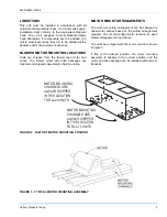
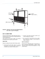
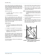
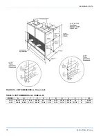
The liquid, suction and drain connections inside the
unit must be piped to the outside. Refer to figure 18 for
unit dimensions or the locations and the dimensions of
the access openings in the unit panel.
Depressurize the system and remove any caps or
discs on the liquid and suction connections that will not
permit a free flow of nitrogen.
Connect a supply of dry nitrogen through a reducing
regulator to an access valve or charging tail. Choose a
procedure that will allow nitrogen to flow continuously
through the system and reach all joints to be brazed.
Begin the refrigerant main piping by installing the liquid
line from the condensing unit to the evaporator liquid
connection, maintaining a flow of nitrogen during all
brazing operations. The filter drier and sight glass must
be located in this line, close to the evaporator. Make
the suction line connection at the evaporator and run
the line to the condensing unit.
After evacuating the holding charge and puncturing the
sealing caps with a small drill bit, unbraze the condens-
ing unit suction disc and connect the line. Maintain a
flow of nitrogen through the liquid line to the evapora-
tor, through the evaporator, back to the condensing
unit and out the suction connection and service port.
NOTE:
Size the suction line outside the evaporator
casing per the line sizing information provided
in the appropriate condensing unit installation
instruction.
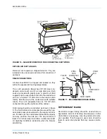
The bulbs for the thermal expansion valve on the
blower units are not factory-installed in their final loca-
tion; they are only temporarily taped for shipment. The
bulb for system one must be fastened in the 4 o’clock
or 8 o’clock position to the system one suction line of
system one leaving the evaporator coil after piping con-
nections are made. Repeat the procedure for system
two, locating the bulb in the 4 o’clock or 8 o’clock posi-
tion to the system two suction line. Use the bulb clamps
from the bag taped to the suction connection inside the
blower unit.
NOTE:
Ensure the TXV bulbs are not crossed
between systems. Undesirable performance
and possible compressor damage may occur.
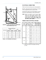
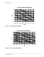
SUPPLY AIR BLOWER ADJUSTMENT
The RPM of the supply air blower will depend on the
required CFM and the external static pressure (both
inlet and outlet) imposed on the unit. If the external
static pressure at the required CFM has been calcu-
lated for the ductwork, the blower RPM and blower
driver kit/motor can then be obtained from the air flow
table.
Once the RPM and motor/kit combination is known, the
number of turns open for the adjustable sheave can be
estimated from Table 3.


