
66339-BIM-C-0206
Unitary Products Group
13
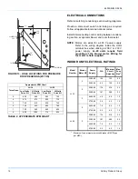
Each unit has a low static and a high static option. The
15 Ton unit offers a 3 hp motor and sheave combina-
tion for the low static option and a 5 hp motor and
sheave combination for the high static option. The 20
Ton offers a 5 hp motor to be used with either the low
or high static sheaves.
Each motor pulley has:
1.
A threaded barrel with two flats (or notched
recesses 180º apart).
2.
A movable flange with one set screw.
After the movable flange has been rotated to the
proper number of turns open, the set screw should be
tightened against the flat on the barrel to lock the mov-
able flange in place. If the pulley includes a locking col-
lar, the locking collar must be loosened to adjust the
setting of the movable flange.
Note the following:
1.
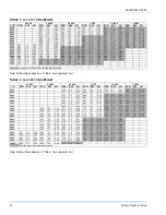
The supply of air CFM must be within the limita-
tions shown in the tables. Be sure not to over amp
the motor.
2.
All pulleys can be adjusted in 1/2 turn increments.
3.
The tension on the belt(s) should be adjusted for a
deflection of 3/16” per foot of belt span with an
applied force of 2 to 3 pounds.
Once the supply air blower motor is operating, adjust
the resistances in both the supply and the return duct
system to balance the air distribution throughout the
conditioned space. The job specification may require
that the balancing be done by someone other than the
equipment installer.
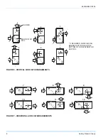
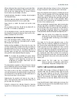
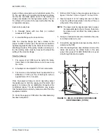
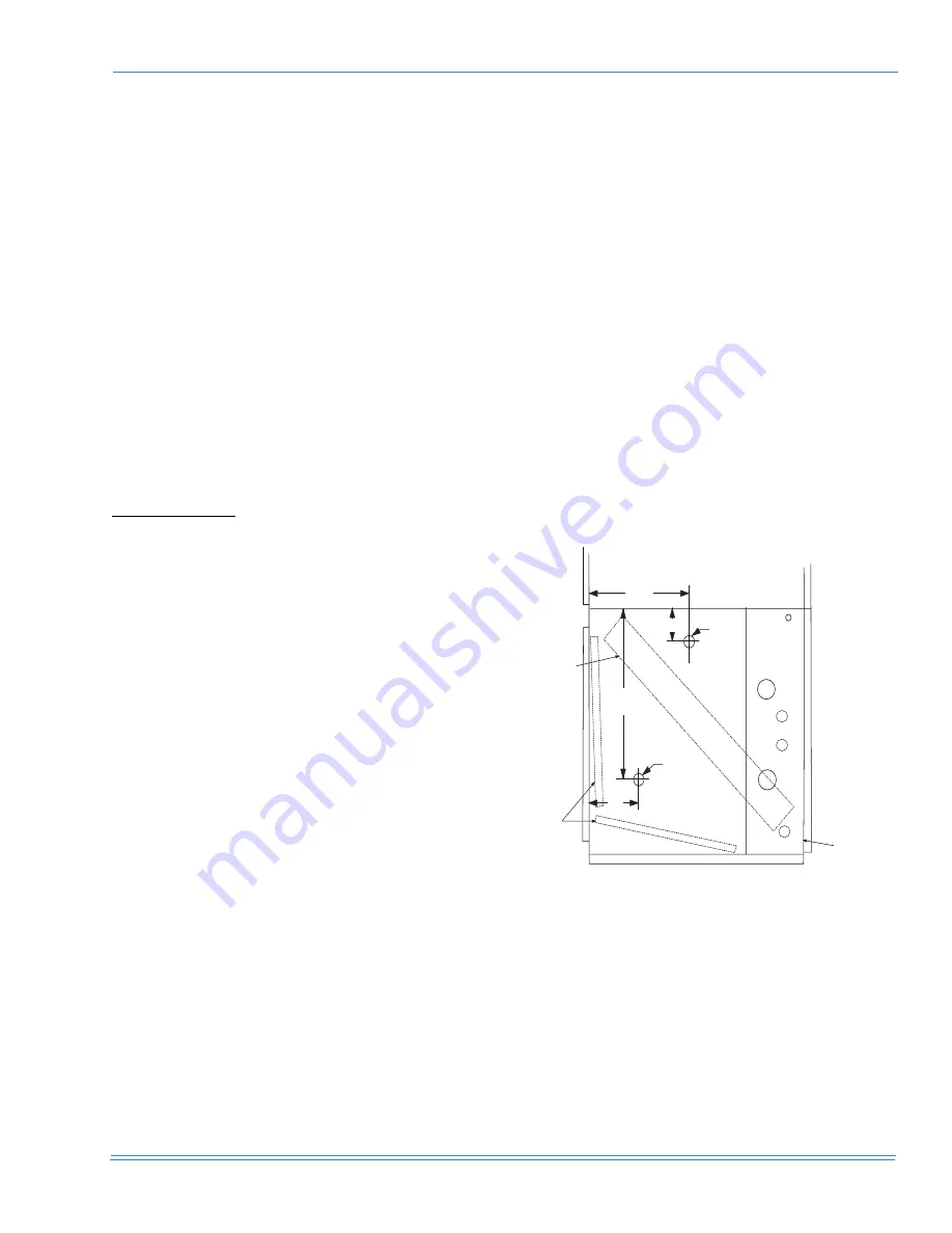
To check the supply air CFM after the initial balancing
has been completed:
1.
Drill two 5/16” holes in the side panel as shown in
figure 10 for the 15 Ton or figure 11 for the 20 Ton.
2.
Insert at least 6” of 1/4” tubing into each of these
holes for sufficient penetration into the air flow on
either side of the indoor coil.
NOTE:
The tubes must be inserted and held in a posi-
tion perpendicular to the air flow so that veloc-
ity pressure will not affect the static pressure
reading.
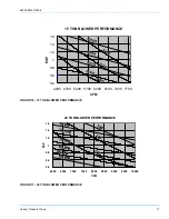
3.
Using an inclined manometer, determine the pres-
sure drop across a dry coil.
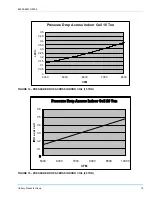
4.
Consult the appropriate coil pressure drop chart to
determine the CFM.
5.
After the readings have been obtained, remove the
tubes and seal up the drilled holes in the side
panel. Dot plugs (P/N 029-13880-000) are avail-
able through Source One parts.
FIGURE 12 - HOLE LOCATIONS FOR PRESSURE
DROP READINGS (15 TON)
5/16"
HOLE
5/16"
HOLE
18"
7"
22"
10"
EVAPORATOR
COIL
FILTERS
COIL SECTION


