
66339-BIM-C-0206
14
Unitary Products Group
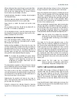
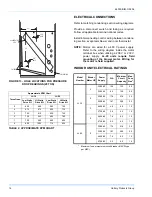
ELECTRICAL CONNECTIONS
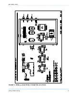
Refer to matching condensing section wiring diagrams.
Provide a disconnect switch and fusing as required.
Follow all applicable local and national codes.
Install interconnecting control wiring between condens-
ing section, evaporator blower and room thermostat.
NOTE:
Motors are wired for a 460 V power supply.
Refer to the wiring diagram inside the motor
terminal box when utilizing a 208 V or 230 V
power supply.
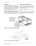
LL-20 units require field
mounting of the blower motor. Wiring for
the motor is field supplied.
INDOOR UNIT ELECTRICAL RATINGS
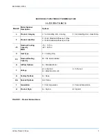
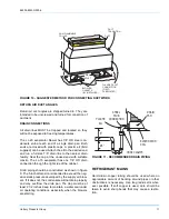
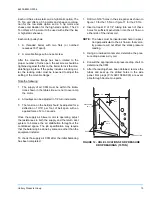
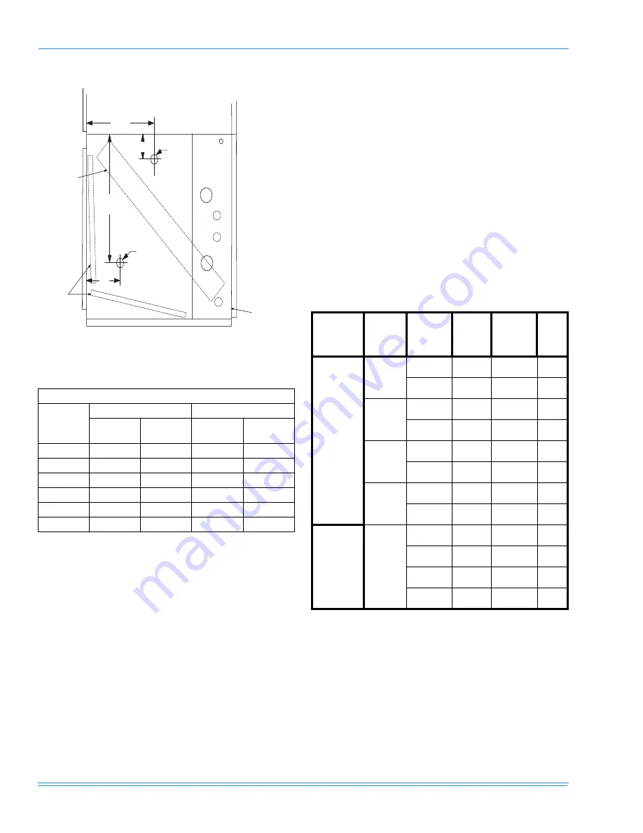
FIGURE 13 - HOLE LOCATIONS FOR PRESSURE
DROP READINGS (20 TON)
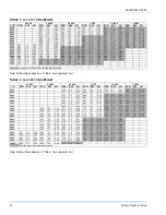
Approximate RPM Chart
Turns Open
LL-15
LL-20
Low Static
Drive Kit
Hi Static
Drive Kit
Low Static
Drive Kit
Hi Static
Drive Kit
5
650
840
580
700
4
675
875
605
730
3
705
910
635
750
2
730
945
660
780
1
750
980
685
805
0
800
1005
715
835
TABLE 2: APPROXIMATE RPM CHART
5/16"
HOLE
5/16"
HOLE
"
7"
25"
14"
EVAPORATOR
COIL
FILTERS
COIL SECTION
22
Model
Number
Blower
Motor HP
Power
Supply
FLA
Minimum
Circuit
Ampacity
Max.
Fuse
Size
1
1.
Maximum fuse or maximum circuit breaker (HACR type
per NEC).
LL-15
3
208-3-60
10.6
13.3
20
230-3-60
9.6
12.0
20
5
208-3-60
17.5
21.9
35
230-3-60
16.7
20.9
35
3
460-3-60
4.8
6.0
15
575-3-60
3.6
4.5
15
5
460-3-60
7.6
9.5
15
575-3-60
5.2
6.5
15
LL-20
5
208-3-60
17.5
21.9
35
230-3-60
16.7
20.9
35
460-3-60
7.6
9.5
15
575-3-60
5.2
6.5
15


