66339-BIM-C-0206
16
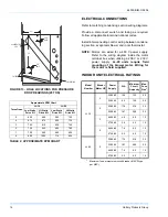
Unitary Products Group
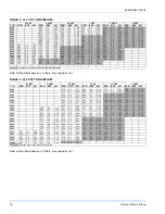
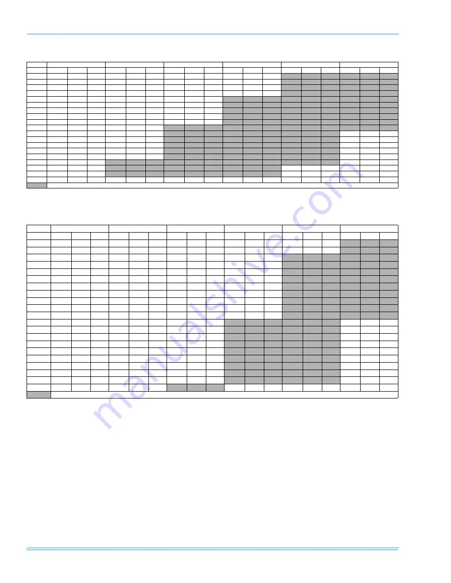
Note: Airflow tables based on 2” filters, dry evaporator coil.
Note: Airflow tables based on 2” filters, dry evaporator coil.
TABLE 3: LL-15 15 TON AIRFLOW
0.4 ESP
0.6 ESP
0.8 ESP
1 ESP
1.2 ESP
1.4 ESP
CFM
RPM
BHP
kW
RPM
BHP
kW
RPM
BHP
kW
RPM
BHP
kW
RPM
BHP
kW
RPM
BHP
kW
4400
660
1.5
1.43
725
1.8
1.69
756
2.0
1.86
886
2.4
2.29
928
2.6
2.4
4600
663
1.6
1.46
733
1.9
1.77
775
2.1
1.99
891
2.6
2.4
937
2.8
2.59
4800
667
1.6
1.5
741
2.0
1.85
794
2.3
2.12
897
2.7
2.52
946
3.0
2.78
5000
671
1.7
1.55
749
2.1
1.94
811
2.4
2.26
903
2.8
2.64
955
3.2
2.98
5200
676
1.7
1.61
758
2.2
2.03
828
2.6
2.39
910
3.0
2.77
963
3.4
3.17
5400
682
1.8
1.68
767
2.3
2.13
844
2.7
2.54
917
3.1
2.91
972
3.6
3.36
5600
688
1.9
1.76
776
2.4
2.24
859
2.9
2.68
924
3.3
3.05
981
3.8
3.56
5800
696
2.0
1.85
785
2.5
2.36
873
3.0
2.83
931
3.4
3.2
990
4.0
3.75
6000
647
1.9
1.78
704
2.1
1.95
794
2.7
2.48
885
3.2
2.98
938
3.6
3.36
998
4.2
3.94
6200
654
2.0
1.83
712
2.2
2.06
804
2.8
2.61
897
3.4
3.14
946
3.8
3.53
1007
4.4
4.14
6400
662
2.0
1.89
722
2.3
2.18
814
2.9
2.74
909
3.5
3.29
954
4.0
3.7
6600
670
2.1
1.97
732
2.5
2.31
824
3.1
2.89
919
3.7
3.45
963
4.1
3.88
6800
679
2.2
2.06
742
2.6
2.45
834
3.2
3.03
928
3.9
3.62
971
4.4
4.07
7000
688
2.3
2.17
754
2.8
2.6
844
3.4
3.19
936
4.1
3.79
980
4.6
4.27
7200
698
2.5
2.3
766
3.0
2.77
855
3.6
3.35
944
4.2
3.96
990
4.8
4.47
7400
708
2.6
2.45
779
3.1
2.94
866
3.8
3.52
950
4.4
4.13
999
5.0
4.68
7600
719
2.8
2.61
792
3.3
3.12
877
4.0
3.7
956
4.6
4.31
7800
730
3.0
2.78
807
3.5
3.31
888
4.1
3.88
960
4.8
4.49
Denotes use of 5 hp motor with high static pulley kit.
TABLE 4: LL-20 20 TON AIRFLOW
0.4 ESP
0.6 ESP
0.8 ESP
1 ESP
1.2 ESP
1.4 ESP
CFM
RPM
BHP
kW
RPM
BHP
kW
RPM
BHP
kW
RPM
BHP
kW
RPM
BHP
kW
RPM
BHP
kW
6000
612
2.0
1.77
681
2.5
2.24
720
2.7
2.44
763
3.1
2.71
6200
617
2.1
1.87
684
2.6
2.32
724
2.9
2.53
767
3.2
2.82
6400
623
2.2
1.97
688
2.7
2.40
727
3.0
2.63
771
3.3
2.94
6600
629
2.3
2.07
692
2.8
2.48
731
3.1
2.73
776
3.4
3.06
6800
634
2.4
2.17
695
2.9
2.57
735
3.2
2.83
781
3.6
3.19
7000
640
2.6
2.27
699
3.0
2.66
739
3.3
2.94
786
3.7
3.32
7200
646
2.7
2.38
703
3.1
2.75
744
3.4
3.05
791
3.9
3.46
7400
582
2.0
1.74
651
2.8
2.48
707
3.2
2.85
748
3.6
3.16
797
4.1
3.61
7600
590
2.1
1.87
657
2.9
2.59
711
3.3
2.95
753
3.7
3.28
803
4.2
3.76
7800
597
2.3
2.00
662
3.0
2.69
715
3.4
3.05
757
3.8
3.40
809
4.4
3.92
8000
603
2.4
2.13
667
3.2
2.80
719
3.6
3.16
762
4.0
3.52
816
4.6
4.08
8200
610
2.5
2.26
673
3.3
2.91
723
3.7
3.26
767
4.1
3.65
8400
617
2.7
2.40
678
3.4
3.02
727
3.8
3.38
772
4.3
3.79
8600
624
2.8
2.53
683
3.5
3.13
731
3.9
3.49
777
4.4
3.92
8800
630
3.0
2.66
689
3.6
3.24
735
4.1
3.61
783
4.6
4.06
9000
637
3.1
2.79
694
3.8
3.35
740
4.2
3.73
788
4.7
4.21
9200
577
2.0
1.80
643
3.3
2.92
699
3.9
3.46
744
4.3
3.85
794
4.9
4.36
9400
584
2.3
2.08
649
3.4
3.06
704
4.0
3.57
748
4.5
3.98
800
5.1
4.51
9600
591
2.6
2.34
655
3.6
3.19
709
4.1
3.68
753
4.6
4.11
806
5.3
4.67
9800
598
2.9
2.59
661
3.7
3.32
714
4.3
3.80
757
4.8
4.25
812
5.4
4.83
10000
605
3.2
2.81
667
3.9
3.46
719
4.4
3.91
Denotes use of high static pulley option.


