
66339-BIM-C-0206
Unitary Products Group
5
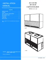
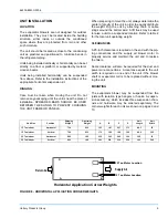
LIMITATIONS
This unit must be installed in accordance with all
national and local safety codes. If no local codes apply,
installation must conform to the appropriate National
Code. The unit is designed to meet National Safety
Code Standards. If components are to be added to a
unit to meet local codes, they are to be installed at the
dealer’s and/or the customer’s expense.
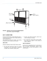
BLOWER MOTOR MOUNTING LOCATIONS
Units are shipped from the factory less motor and
drives. The blower motor and drive packages are
ordered and shipped separately for field mounting.
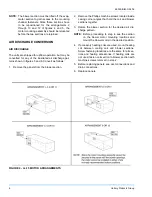
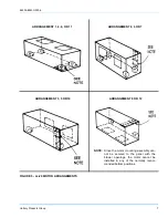
MOTOR MOUNT ARRANGEMENTS
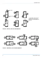
The motor mounting arrangement can be changed to
allow motor access based on the airflow arrangement
required. The recommended motor location for each
blower arrangement is as follows.
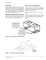
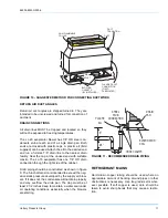
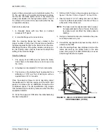
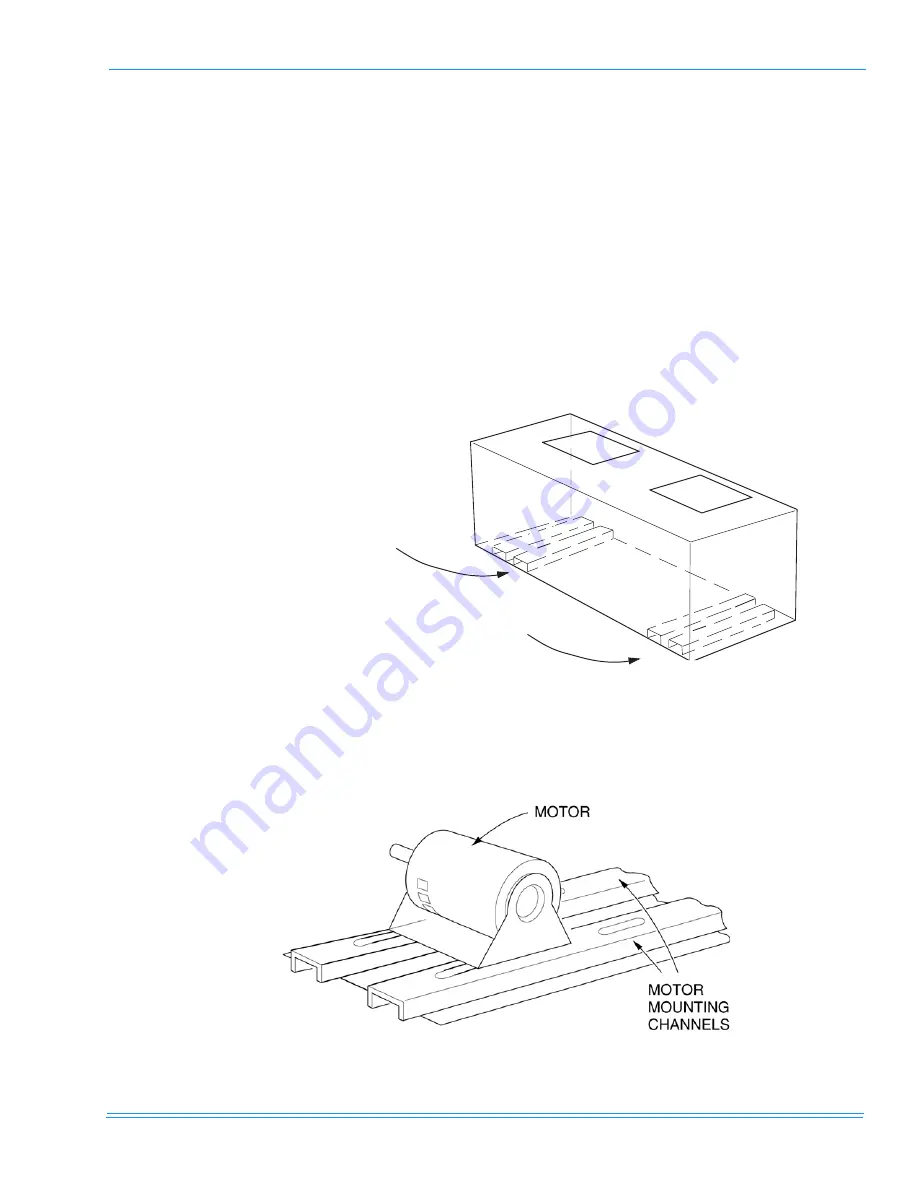
The units are shipped with the motor mount as shown
in figure 3.
If this is the desired position, the motor mounting
assembly is already in the correct position and the
motor and drive package can be installed without mod-
ifications.
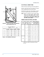
FIGURE 2 - FACTORY MOTOR MOUNTING POSITION
MOTOR MOUNTING
CHANNELS ARE
ALWAYS SHIPPED
IN THIS LOCATION
FOR LL-20 UNITS
MOTOR MOUNTING
CHANNELS ARE
ALWAYS SHIPPED
IN THIS LOCATION
FOR LL-15 UNITS
FIGURE 3 - TYPICAL MOTOR MOUNTING ASSEMBLY


