
66339-BIM-C-0206
6
Unitary Products Group
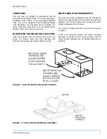
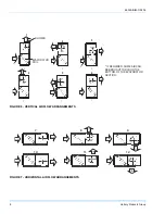
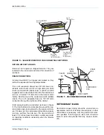
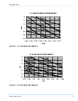
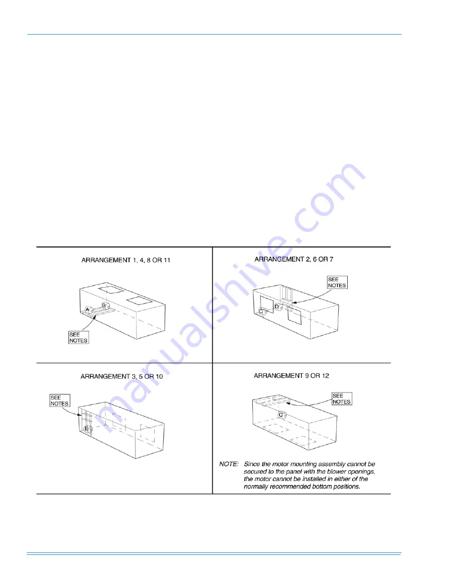
NOTE:
The blower section must be lifted off the evap-
orator section to gain access to the mounting
channel fasteners. Since these sections have
to be repositioned for the arrangements 2
through 10 and 12 of figures 4 and 5, the
motor mounting assembly should be relocated
before the two sections are rejoined.
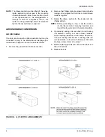
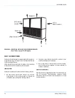
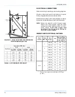
AIR DISCHARGE CONVERSION
AIR DISCHARGE
The units are shipped for upflow operation, but may be
converted for any of the illustrated air discharge pat-
terns shown in figures 5 and 6. Convert as follows:
1.
Remove the panels from the blower section.
2.
Remove the Phillips machine screws located inside
casing corner angles that hold the coil and blower
sections together.
3.
Rotate the blower section for the desired air dis-
charge pattern.
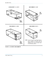
NOTE:
Before proceeding to step 4, see the section
on the blower motor mounting locations and
mount the blower motor in the desired position.
4.
If accessory heating coils are used, mount heating
coil between cooling coil and blower sections.
Screw fastening locations are the same for all sec-
tions and heating accessories. If heating coils are
not used, fasten coil section to blower section with
machine screws removed in step 2.
5.
Before replacing panels, see duct connections and
drain connections.
6.
Replace panels.
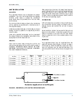
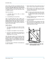
FIGURE 4 - LL-15 MOTOR ARRANGEMENTS


