
66339-BIM-C-0206
Unitary Products Group
9
UNIT INSTALLATION
LOCATION
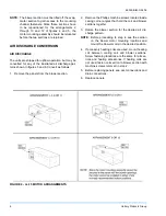
The evaporator blowers are not designed for outdoor
installation. They must be located inside the building
structure, either inside or outside the conditioned
space where they are protected from rain and other
such moisture.
The unit should be located as close to the condensing
unit as practical and positioned to minimize bends in
the refrigerant piping.
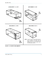
Units being installed vertically or horizontally can be set
directly on a floor or platform, or supported by metal or
wooden beams.
Units being installed horizontally can be suspended
from above. Refer to the installation instructions of the
appropriate horizontal suspension kit.
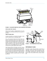
RIGGING
Care must be taken when moving the unit. Do not
remove any packaging until the unit is near the place of
installation. SPREADER BARS SHOULD BE USED
BETWEEN THE SLINGS TO PREVENT CRUSHING
THE UNIT FRAME OR PANELS.
When preparing to move the unit, always determine the
center of gravity of the unit in order to equally distribute
the weight. Rig the unit by attaching chain or cable
slings around the bottom skid. A lift truck may be used
to raise a unit to a suspended location. Refer to table 2
for the total unit operating weight.
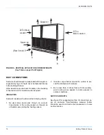
CLEARANCES
A 25-inch clearance is required on the end with the pip-
ing connections and the supply air blower motor to
properly service and maintain the unit and to replace
the filters.
Some clearance will also be required for the duct and
power wire connections. A clearance equal to the unit
width is required on one end of the unit if the blower
shaft or evaporator coil is to be replaced without mov-
ing the unit.
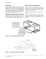
MOUNTING
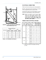
The evaporator blower may be suspended from the
joists with isolation type hangers or hooks. A suspen-
sion accessory, which includes three suspension chan-
nels and hardware, may be ordered separately. The
corner weights for each unit are shown on pages 9 and
10.
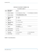
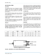
Unit Size
Position
Shipping
Weight
Operating
Weight
A
B
C
D
Unit
Length
Unit
Width
15 Ton Indoor
Horizontal
720
830
155
187
207
171
89.5
59
15 Ton Indoor
Vertical
720
830
172
194
188
166
89.5
29.5
20 Ton Indoor
Horizontal
990
1115
230
345
249
166
100
74
20 Ton Indoor
Vertical
990
1115
263
238
232
256
100
36.5
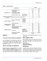
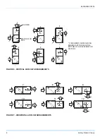
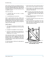
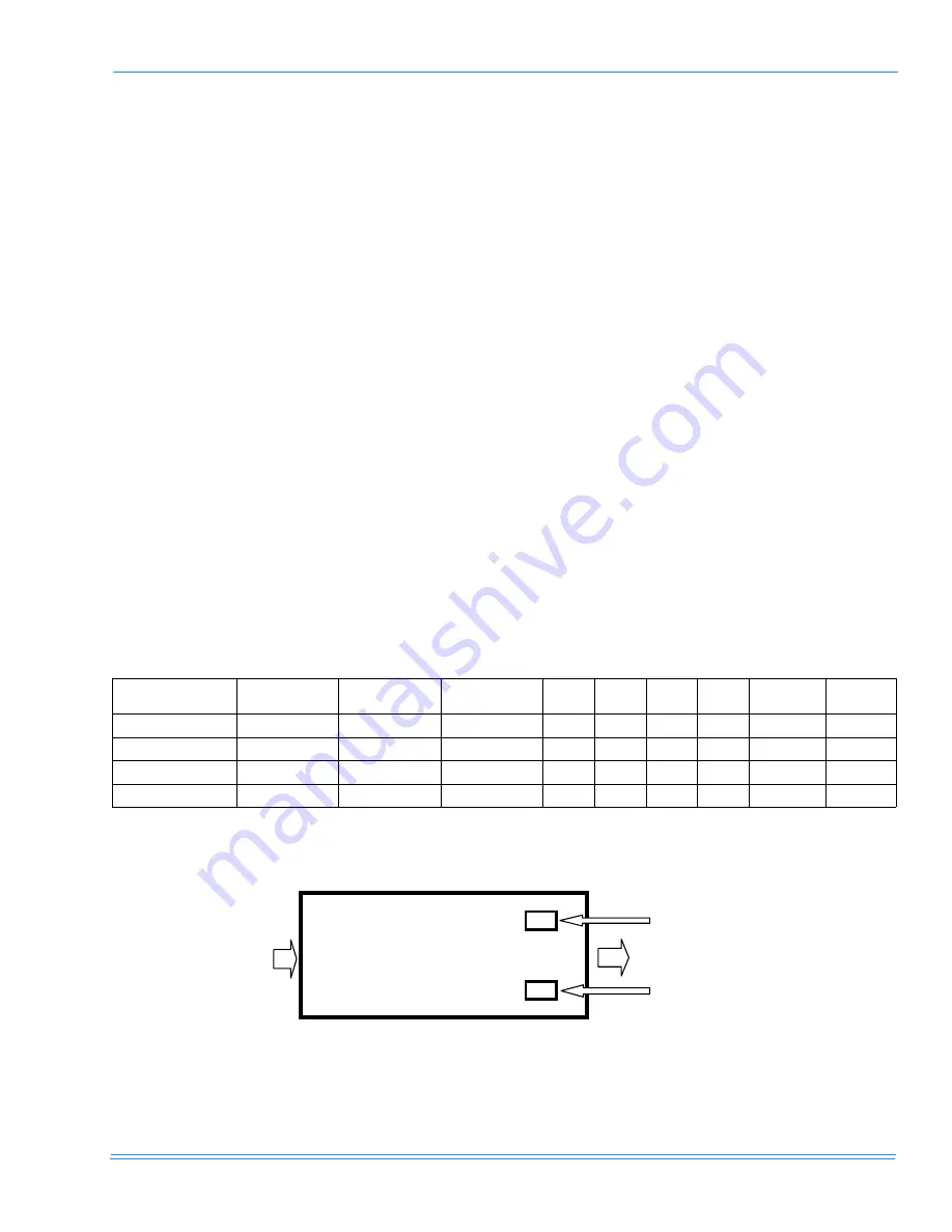
FIGURE 8 - HORIZONTAL APPLICATION CORNER WEIGHTS
D
C
20 Ton Motor Location
Return Air
A
B
Horizontal Application Corner Weights
15 Ton Motor Location
Supply Air


