Subject to change without notice. Printed in U.S.A.
035-14446-000 Rev. B (1002)
Copyright
©
by York International Corp. 2002. All rights reserved.
Supersedes: 035-14446-000 Rev. A (0301)
Unitary
5005 Norman
Product
York
OK
Group
Drive
73069
6.
Turn unit electrical disconnect switch to ON. The com-
bustion blower should start and the hot surface igniter
should start glowing.
7.
After air has been purged from the gas supply line, igni-
tion should occur. Shortly after ignition, the manifold and
gas inlet pressures can be checked on the manometers.
Main burner ignition may be delayed on the first ignition
cycle due to air in the gas manifold.
8.
Adjust manifold pressure to specifications shown in
Table 6. This setting will result in an input which is prop-
erly derated for your altitude. Supply gas must be within
the range shown in Table 6. If required, adjust the incom-
ing regulator spring so that the pressure falls within the
range.
9.
Observe several ignition cycles. All main burners must
ignite without delayed ignition or burning at the orifices. If
delayed ignition is observed, verify that the igniter is
properly mounted (not loose or crooked on bracket, and
that bracket screws are not loose).
10. If burning at the orifices, excessive yellow tipping, or
excessive noise is observed during any phase of main
burner operation, correct unit operation.
11. With the main burners ignited, check for gas leaks,
especially in the following locations: gas valve inlet and
outlet connections, manifold union in the burner compart-
ment, and main burner orifices where they thread into
the manifold. Repair any leaks found and recheck.
12. Operate the furnace for 15 minutes and measure the
supply and return air temperatures. Verify that the tem-
perature rise (supply air - return air rise) is within the
allowable range. See the unit data plate for the minimum/
maximum allowable temperature rise. If the measured
rise is in excess of the maximum shown on the data
plate, a higher blower speed must be selected. See the
unit wiring diagram to make this change.
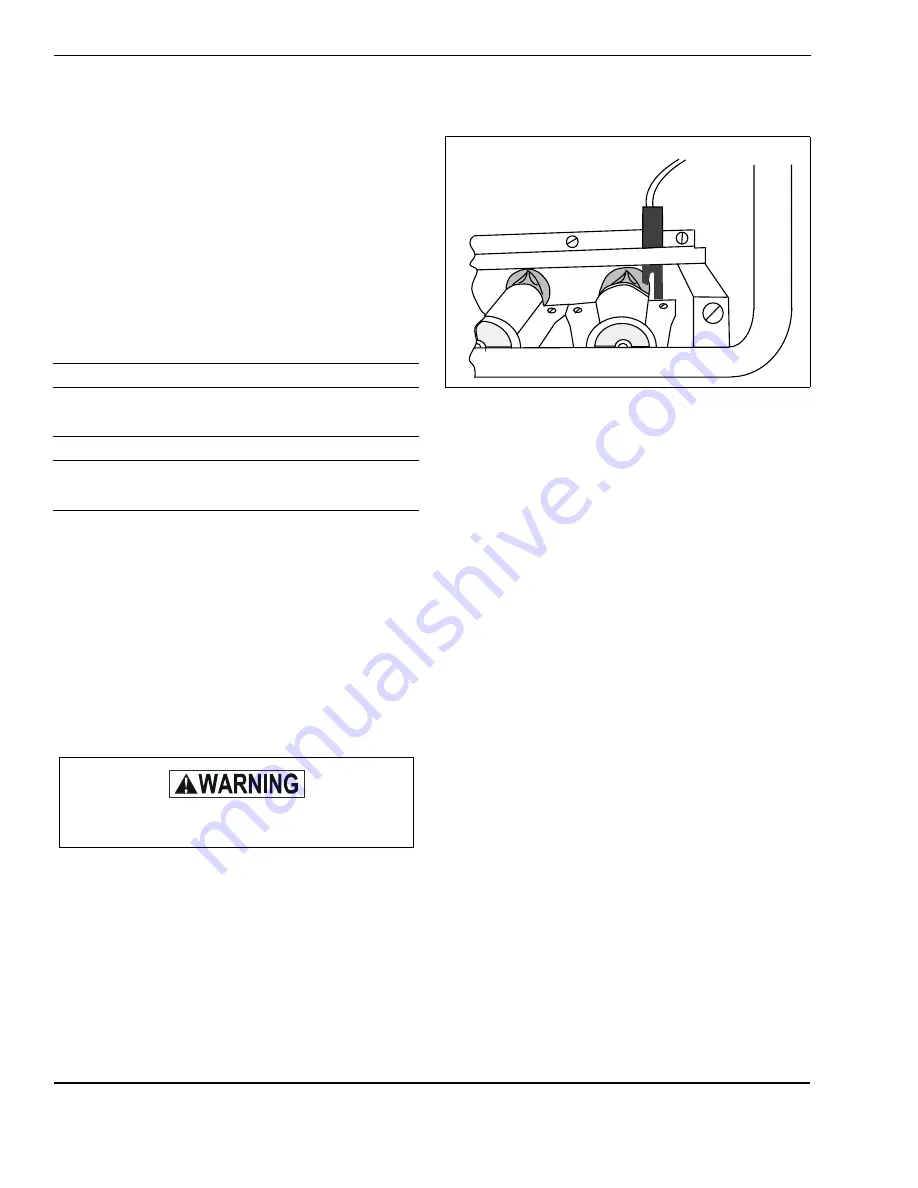
13. During unit operation, the main burner appearance and
igniter location should be as shown below:
14. With the main burners off, disconnect the manometers
and replace the plugs. Check for gas leakage at the
plugs.
15. Replace all access panels.
LABELS
1.
Remove label 035-11635-000 from the shipping box.
Check the Normal to High Altitude.
NOTE:
If the unit has been converted from natural gas to pro-
pane (LP), place the new label over the existing label and fill
in the appropriate information.
2.
Under "Rating After Conversion", write in the following:
a.
Orifice size, as stamped on the orifice
b.
Maximum inlet pressure
c.
Minimum inlet pressure
d.
Manifold pressure for both low and high inputs
e.
Input ratings, same as on the rating plate
f.
Outlet ratings, same as on the rating plate
3.
Under "Changes After Conversion", write in the follow-
ing:
a.
Kit number, located on the outside of the box.
b.
Unit model
c.
Stamp or write in the name of the organization mak-
ing conversion, address, city, state, month and year.
4.
Remove label backing and affix label adjacent to the Rat-
ing Plate.
5.
On propane (LP) conversions, affix the corresponding
gas valve label (provided in the conversion kit) to the
valve.
Table 6:
GAS PRESSURES
NATURAL GAS
Inlet Gas Pressure Must Be
at 4.5” - 13.9” WC at Furnace
Set Manifold Pressure at 3.5” WC
PROPANE (LP) GAS
Inlet Gas Pressure Must Be
at 11” - 13.9” WC at Furnace
Set Manifold Pressure at 10” WC
Do not use an open flame or any source of ignition
to check for leaks.
FIGURE 1:
Proper Burner Flame Appearance
BLUE CONE PORTION OF
FLAME SHOULD ENTER
HEAT EXCHANGER TUBE


