
035-19656-003 Rev. A (1004)
EFFICIENCY
RATING
CERTIFIED
This product was manufactured
in a plant whose quality system
is certified/registered as being
in conformity with ISO 9001.
HIGH EFFICIENCY
TUBULAR HEAT EXCHANGER SERIES
MODELS: PS8 / FC8S / FL8S / LC8S / LL8S
(Single Stage Upflow / Horizontal / LoNOx)
40 - 130 MBH INPUT
(11.72 - 38.10 KW) INPUT
INSTALLATION MANUAL
SECTION I: SAFETY
This is a safety alert symbol. When you see this symbol on
labels or in manuals, be alert to the potential for personal
injury.
Understand and pay particular attention to the signal words
DANGER
,
WARNING
, or
CAUTION
.
DANGER
indicates an
imminently
hazardous situation, which, if not
avoided,
will result in death or serious injury
.
WARNING
indicates a
potentially
hazardous situation, which, if not
avoided,
could result in death or serious injury
.
CAUTION
indicates a potentially hazardous situation, which, if not
avoided
may result in minor or moderate injury.
It is also used to
alert against unsafe practices and hazards involving only property dam-
age.
Improper installation may create a condition where the operation of
the product could cause personal injury or property damage.
Improper installation, adjustment, alteration, service or mainte-
nance can cause injury or property damage. Refer to this manual
for assistance or for additional information, consult a qualified con-
tractor, installer or service agency.
This product must be installed in strict compliance with the installa-
tion instructions and any applicable local, state, and national codes
including, but not limited to building, electrical, and mechanical
codes.
TABLE OF CONTENTS
SAFETY . . . . . . . . . . . . . . . . . . . . . . . . . . . . . . . . . . . . . . . . . . . . . . . . 1
DUCTWORK . . . . . . . . . . . . . . . . . . . . . . . . . . . . . . . . . . . . . . . . . . . . 3
FILTERS . . . . . . . . . . . . . . . . . . . . . . . . . . . . . . . . . . . . . . . . . . . . . . . 7
GAS PIPING . . . . . . . . . . . . . . . . . . . . . . . . . . . . . . . . . . . . . . . . . . . . 8
ELECTRICAL POWER . . . . . . . . . . . . . . . . . . . . . . . . . . . . . . . . . . . . 9
TWINNING AND STAGING . . . . . . . . . . . . . . . . . . . . . . . . . . . . . . . .11
VENT SYSTEM . . . . . . . . . . . . . . . . . . . . . . . . . . . . . . . . . . . . . . . . .13
SAFETY CONTROLS . . . . . . . . . . . . . . . . . . . . . . . . . . . . . . . . . . . .18
START-UP AND ADJUSTMENTS . . . . . . . . . . . . . . . . . . . . . . . . . . .19
WIRING DIAGRAM . . . . . . . . . . . . . . . . . . . . . . . . . . . . . . . . . . . . . .26
LIST OF FIGURES
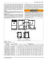
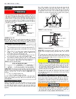
Dimensions . . . . . . . . . . . . . . . . . . . . . . . . . . . . . . . . . . . . . . . . . . . . . 5
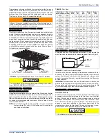
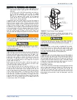
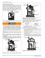
Furnace Base Rectangular Perforated Panel . . . . . . . . . . . . . . . . . . . 6
Typical Attic Installation . . . . . . . . . . . . . . . . . . . . . . . . . . . . . . . . . . . . 6
Typical Suspended Furnace / Crawl Space Installation . . . . . . . . . . . . 7
Side Return Cutout Markings . . . . . . . . . . . . . . . . . . . . . . . . . . . . . . . . 7
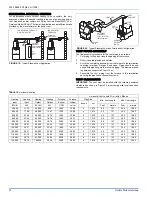
Gas Valve . . . . . . . . . . . . . . . . . . . . . . . . . . . . . . . . . . . . . . . . . . . . . . . 8
Upflow Gas Piping . . . . . . . . . . . . . . . . . . . . . . . . . . . . . . . . . . . . . . . . 8
Horizontal Gas Piping . . . . . . . . . . . . . . . . . . . . . . . . . . . . . . . . . . . . . 8
Electrical Wiring . . . . . . . . . . . . . . . . . . . . . . . . . . . . . . . . . . . . . . . . . 10
Line Wiring Connections . . . . . . . . . . . . . . . . . . . . . . . . . . . . . . . . . . 10
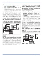
Heating and Cooling Thermostat Connections . . . . . . . . . . . . . . . . . 10
Heating and Two-Stage Cooling Thermostat Connections . . . . . . . . 10
Accessory Connections . . . . . . . . . . . . . . . . . . . . . . . . . . . . . . . . . . . 10
Typical Twinned Furnace Application . . . . . . . . . . . . . . . . . . . . . . . . 11
Single Stage Twinning Wiring Diagram . . . . . . . . . . . . . . . . . . . . . . . 12
Two-Stage Twinning Wiring Diagram . . . . . . . . . . . . . . . . . . . . . . . . . 12
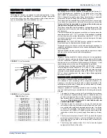
Vent Termination . . . . . . . . . . . . . . . . . . . . . . . . . . . . . . . . . . . . . . . . 13
Vent Termination . . . . . . . . . . . . . . . . . . . . . . . . . . . . . . . . . . . . . . . .13
Typical Sidewall Vent Application . . . . . . . . . . . . . . . . . . . . . . . . . . . .14
Typical Sidewall Vent and Termination Configuration . . . . . . . . . . . .14
Home Layout . . . . . . . . . . . . . . . . . . . . . . . . . . . . . . . . . . . . . . . . . . .15
Combustion Airflow Path Through The Furnace Casing
to the Burner Box . . . . . . . . . . . . . . . . . . . . . . . . . . . . . . . . . . . . . . . .16
Alternate Air Intake, Air Outlet and Chimney Connections . . . . . . . . .16
Air Inlet, Outlet and Chimney Connections . . . . . . . . . . . . . . . . . . . . .16
Typical Chimney Connections . . . . . . . . . . . . . . . . . . . . . . . . . . . . . .16
Horizontal Air Inlet, Outlet and Chimney Connections . . . . . . . . . . . .17
Outside and Ambient Combustion Air . . . . . . . . . . . . . . . . . . . . . . . . .17
Pressure Switch Tubing Routing . . . . . . . . . . . . . . . . . . . . . . . . . . . .19
Gas Valve . . . . . . . . . . . . . . . . . . . . . . . . . . . . . . . . . . . . . . . . . . . . . .21
Reading Gas Pressure . . . . . . . . . . . . . . . . . . . . . . . . . . . . . . . . . . . .21
Typical Heat/Cool Speed Tap Connections . . . . . . . . . . . . . . . . . . . .22
Wiring Diagram . . . . . . . . . . . . . . . . . . . . . . . . . . . . . . . . . . . . . . . . . .26
LIST OF TABLES
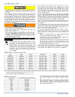
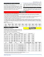
Unit Clearances to Combustibles . . . . . . . . . . . . . . . . . . . . . . . . . . . . . 3
Minimum Duct Sizing For Proper Airflow . . . . . . . . . . . . . . . . . . . . . . . 4
Round Duct Size . . . . . . . . . . . . . . . . . . . . . . . . . . . . . . . . . . . . . . . . . 4
Cabinet and Duct Dimensions . . . . . . . . . . . . . . . . . . . . . . . . . . . . . . . 5
Filter Sizes . . . . . . . . . . . . . . . . . . . . . . . . . . . . . . . . . . . . . . . . . . . . . . 7
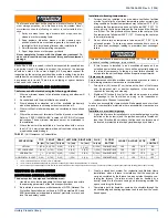
Inlet Gas Pressure Range . . . . . . . . . . . . . . . . . . . . . . . . . . . . . . . . . . 8
High Altitude Conversion . . . . . . . . . . . . . . . . . . . . . . . . . . . . . . . . . . . 9
Ratings & Physical / Electrical Data - Upflow Models . . . . . . . . . . . . . 9
Roof Pitch . . . . . . . . . . . . . . . . . . . . . . . . . . . . . . . . . . . . . . . . . . . . . . 13
Horizontal Venting . . . . . . . . . . . . . . . . . . . . . . . . . . . . . . . . . . . . . . .14
Estimated Free Area . . . . . . . . . . . . . . . . . . . . . . . . . . . . . . . . . . . . . .16
Free Area . . . . . . . . . . . . . . . . . . . . . . . . . . . . . . . . . . . . . . . . . . . . . .17
Unconfined Space Minimum Area in Square Inch . . . . . . . . . . . . . . .17
Inlet Gas Pressure Range . . . . . . . . . . . . . . . . . . . . . . . . . . . . . . . . .21
Nominal Manifold Pressure . . . . . . . . . . . . . . . . . . . . . . . . . . . . . . . . .21
Filter Performance - Pressure Drop Inches W.C. and (kPa) . . . . . . . .22
Blower Performance CFM - Upflow (without filter) - Bottom Return . .23
Blower Performance CFM - Upflow (without filter) - Left Side Return 24


