background image

035-19656-003 Rev. A (1004)

10

Unitary Products Group

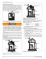
SUPPLY VOLTAGE CONNECTIONS

1.

Provide a power supply separate from all other circuits. Install
overcurrent protection and disconnect switch per local/national
electrical codes. The switch should be close to the unit for conve-
nience in servicing. With the disconnect or fused switch in the OFF
position, check all wiring against the unit wiring label. Refer to the
wiring diagram in this instruction.
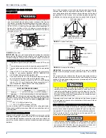
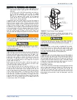
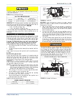
2.

Remove the screws retaining the wiring box cover. Route the
power wiring through the opening in the unit into the junction box
with a conduit connector or other proper connection. In the junc-
tion box there will be three wires, a Black Wire, a White Wire and a
Green Wire. Connect the power supply as shown on the unit-wir-
ing label on the inside of the blower compartment door or the wir-
ing schematic in this section. The black furnace lead must be
connected to the L1 (hot) wire from the power supply. The white
furnace lead must be connected to neutral. Connect the green fur-
nace lead (equipment ground) to the power supply ground. An
alternate wiring method is to use a field provided 2” (5.1 cm) x 4”
(10.2 cm) box and cover on the outside of the furnace. Route the
furnace leads into the box using a protective bushing where the
wires pass through the furnace panel. After making the wiring con-
nections replace the wiring box cover and screws. Refer to Figure
11.

3.

The furnace's control system requires correct polarity of the power
supply and a proper ground connection. Refer to Figure 12.

IMPORTANT: 

The power connection leads and wiring box may be relo-

cated to the left side of the furnace. Remove the screws and cut wire tie
holding excess wiring. Reposition on the left side of the furnace and fas-
ten using holes provided.

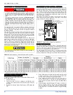
LOW VOLTAGE CONTROL WIRING CONNECTIONS

Install the field-supplied thermostat by following the instructions that
come with the thermostat. With the thermostat set in the OFF position
and the main electrical source disconnected, connect the thermostat
wiring from the wiring connections on the thermostat to the terminal
board on the ignition module, as shown in Figures 13 or 14. Electronic
thermostats may require the common wire to be connected as shown
with the dashed line in Figures 13 or 14. Apply strain relief to thermostat
wires passing through cabinet. If air conditioning equipment is installed,
use thermostat wiring to connect the Y and C terminals on the furnace
control board to the proper wires on the condensing unit (unit outside).
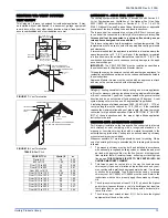
Refer to Figure 13. For two-stage condensing units, connect the Y1, Y2
and C terminals on the furnace control to the proper wires on the out-
side unit. See Figure 14.

IMPORTANT: 

Set the heat anticipator in the room thermostat to 0.10

amps. Setting it lower will cause short cycles. Setting it higher will cause
the room temperature to exceed the set points.

IMPORTANT: 

Some electronic thermostats do not have adjustable heat

anticipators. They may have other type cycle rate adjustments. Follow
the thermostat manufacturer's instructions.

The 24-volt, 40 VA transformer is sized for the furnace components
only, and should not be connected to power auxiliary devices such as
humidifiers, air cleaners, etc. The transformer may provide power for an
air conditioning unit contactor.

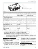
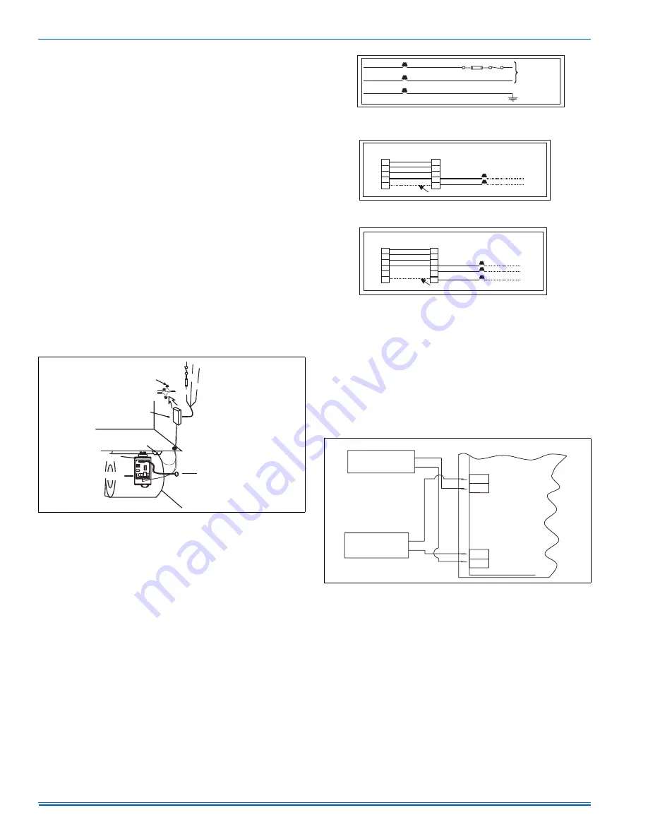
ACCESSORY CONNECTIONS

The furnace control will allow power-switching control of various acces-
sories. Refer to Figure 15, for connection details.

ELECTRONIC AIR CLEANER CONNECTION

Two 1/4” (6.4 mm) spade terminals (EAC and EAC N) for electronic air
cleaner connections are located on the control board. The terminals
provide 115 VAC (1.0 amp maximum) during circulating blower opera-
tion.

HUMIDIFIER CONNECTION

Two 1/4” (0.64 cm) spade terminals (HUM and HUM N) for humidifier
connections are located on the control board. The terminals provide 115
VAC (1.0 amp maximum) during heating system operation.
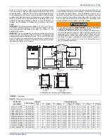
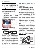
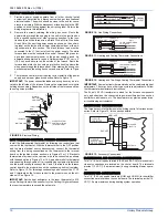
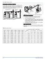
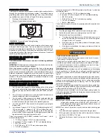
 FIGURE 9:  

Electrical Wiring

Y W RGC

CLASS 2 SYSTEM
CONTROL WIRING
TO THERMOSTAT

TRANSFORMER

IGNITION MODULE

BURNER COMPARTMENT

BLOWER COMPARTMENT

DOOR SWITCH

JUNCTION
BOX

BLK/BLK
WHT/WHT
GRN/GRN

L1
HOT

WHT

N

GND

GRN

BLK

 FIGURE 10:  

Line Wiring Connections
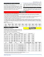
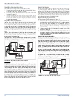
 FIGURE 11:  

Heating and Cooling Thermostat Connections

 FIGURE 12:  

Heating and Two-Stage Cooling Thermostat Connections

 FIGURE 13:  

Accessory Connections

BLK

WHT

GRN

BLK (HOT)

WHT (NEUTRAL)

GRN

NOMINAL
120 VOLT

ROOM
THERMOSTAT

FURNACE
CONTROL

CONDENSING
UNIT

TO AIR CONDITIONER
CONTROLS

R

W

G

Y
C

R

W

G

Y
C

COMMON T’STAT CONNECTION

ROOM
THERMOSTAT

FURNACE
CONTROL

CONDENSING
UNIT

TO AIR CONDITIONER
CONTROLS

R

W

G

Y1

C

R

W

G

C
COMMON T’STAT CONNECTION

Y2

Y1
Y2

115 VOLT
HUMIDIFER

115 VOLT
ELECTRONIC
AIR CLEANER

EAC HOT

HUM. HOT

BLK

WHT

EAC

HUM

NEUTRALS

SWITCHED
CIRCUITS

BLK

WHT

Summary of Contents for PS8

Page 1: ...AL POWER 9 TWINNING AND STAGING 11 VENT SYSTEM 13 SAFETY CONTROLS 18 START UP AND ADJUSTMENTS 19 WIRING DIAGRAM 26 LIST OF FIGURES Dimensions 5 Furnace Base Rectangular Perforated Panel 6 Typical Atti...

Page 2: ...all instructions in this manual can result in furnace malfunction death personal injury and or property damage Furnaces for installation on combustible flooring shall not be installed directly on carp...

Page 3: ...e over clear ances for combustible materials where accessibility clearances are greater Installation in a residential garage 1 A gas fired furnace for installation in a residential garage must be inst...

Page 4: ...he total square inch of duct attached to the furnace plenum is 300 8 square inch This exceeds the recommended 280 square inch of duct In this example the duct system attached to the plenum has a suffi...

Page 5: ...above the maximum supply air temperature will cause the heat exchanger to overheat causing premature heat exchanger failure Improper duct sizing dirty air filters incorrect manifold pressure incorrect...

Page 6: ...thout a Cooling Coil Cabinet When installing this appliance the furnace must be installed so as to create a closed duct system the supply duct system must be con nected to the furnace outlet and the s...

Page 7: ...the filter exter nal to the cabinet IMPORTANT Some accessories such as electronic air cleaners and pleated media may require a larger side opening Follow the instruc tions supplied with that accessory...

Page 8: ...ge to the furnace or some of its components that will result in property damage and loss of life FIGURE 6 Gas Valve INLET WRENCH BOSS INLET PRESSURE PORT O N O FF ON OFF SWITCH Shown in ON position MA...

Page 9: ...conversions are required in order for the appliance to satisfactory meet the application An authorized distributor or dealer must make all gas conversions In Canada a certified conversion station or o...

Page 10: ...Figures 13 or 14 Apply strain relief to thermostat wires passing through cabinet If air conditioning equipment is installed use thermostat wiring to connect the Y and C terminals on the furnace contr...

Page 11: ...e mixing device must be installed before any ducts that supply air to occupied spaces Twinning causes both indoor fans to operate simultaneously If a mixing device is not used any ducts that are conne...

Page 12: ...Staging The single wire twinning feature of this board can also be used for stag ing of two furnaces With this feature a single wire is connected between the TWIN terminal on one furnace board to the...

Page 13: ...ted for high altitude operation Refer to SECTION IV GAS PIP ING of these instructions and the proper high altitude application instruction for details VENTING INTO AN EXISTING CHIMNEY For Category I i...

Page 14: ...FAN ASSISTED FURNACE WATER HEATER FAN ASSISTED FURNACES VENT PIPE HOT WATER TANK FURNACE OPTIONAL SIDEWALL VENT SYSTEM field supplied EXTERIOR VENT HOOD FIGURE 20 Typical Sidewall Vent and Terminatio...

Page 15: ...ent sagging The vent system may be supported by the use of clamps or hangers secured to a permanent part of the structure every 4 ft 1 22 m FAN ASSISTED COMBUSTION SYSTEM An appliance equipped with an...

Page 16: ...sub tracting the blockage area of all fixed louvers grilles or screens from the gross area of the opening 2 Apertures in a fixed louver a grille or screen shall have no dimen sion smaller than 0 25 0...

Page 17: ...horizontally from the burner level of the appliance Refer to AIR SOURCE FROM OUTDOORS AND VENT AND SUPPLY AIR SAFETY CHECK in these instructions for additional information and safety check procedure 2...

Page 18: ...he combustion air blower heat exchanger or a blocked vent pipe connection Corrective action is required These are manual reset controls that must be reset before operation can continue CARBON MONOXIDE...

Page 19: ...ngth x 1 8 0 3 cm diameter tubing 1 5 16 0 8 cm tee 1 5 16 0 8 cm x 1 8 3 175 mm reducing coupling 1 1 8 0 3 cm adapter There is a accessory kit 1PK0602 available from Source 1 which has the following...

Page 20: ...divided by the time it took to measure 2 cubic ft 0 0566 m3 of gas from the gas meter For Propane LP Gas multiply the Heat content of the gas MJ m3 or Default 93 14 times 0 00283 m3 of gas measured a...

Page 21: ...e the unit back in operation 3 Adjust manifold pressure by adjusting gas valve regulator screw for the appropriate gas per the following IMPORTANT If gas valve regulator is turned in clockwise manifol...

Page 22: ...turn opening size in square inches to determine the proper filter pres sure drop 3 Determine the External System Static Pressure ESP without the filter 4 Select a filter pressure drop from the table b...

Page 23: ...7 Medium 1470 1450 1440 1430 1390 1360 1310 1270 1220 1150 41 6 41 1 40 8 40 5 39 4 38 5 37 1 36 0 34 5 32 6 Low 1260 1260 1260 1260 1250 1200 1150 1110 1070 1010 35 7 35 7 35 7 35 7 35 4 34 0 32 6 31...

Page 24: ...52 4 48 4 44 5 36 8 Medium Low 1690 1690 1650 1610 1540 1480 1410 1280 1170 1030 47 9 47 9 46 7 45 6 43 6 41 9 39 9 36 2 33 1 29 2 Low 1350 1330 1310 1290 1260 1220 1150 1050 970 860 38 2 37 7 37 1 3...

Page 25: ...s SEE CHART PAGE 6 1PS0302 1PS0311 1PS0312 1BR0314 EXTERNAL BOTTOM RETURN FILTER with High Velocity Filter for Horizontal Application for Upflow Bottom Return Application 14 1 2 CABINETS 1BR0317 17 1...

Page 26: ...035 19656 003 Rev A 1004 26 Unitary Products Group SECTION X WIRING DIAGRAM FIGURE 32 Wiring Diagram...

Page 27: ...035 19656 003 Rev A 1004 Unitary Products Group 27 NOTES...

Page 28: ...e without notice Printed in U S A 035 19656 003 Rev A 1004 Copyright by York International Corp 2004 All rights reserved Supersedes 035 19656 002 Rev A 0704 Unitary 5005 Norman Product York OK Group D...

Reviews: