


035-19656-003 Rev. A (1004)
Unitary Products Group
13
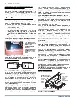
SECTION VII: VENT SYSTEM
VENT SAFETY
This Category I, furnace is designed for residential application. It may
be installed without modification in a basement, garage, equipment
room, alcove, attic or any other indoor location where all required clear-
ance to combustibles and other restrictions are met.
CATEGORY 1 - 450 F. MAX. VENT TEMP.
The venting system must be installed in accordance with Section 5.3,
Air for Combustion and Ventilation, of the National Fuel Gas Code
Z223.1/NFPA 54 (latest edition), or Sections 7.2, 7.3 or 7.4 of CSA
B149.1, National Gas and Propane Codes (latest edition) or applicable
provisions of the local building code and these instructions.
The furnace shall be connected to any type of B, BW or L vent connec-
tor, and shall be connected to a factory-built or masonry chimney.
The
furnace shall not be connected to a chimney flue serving a sepa-
rate appliance designed to burn solid fuel.
The furnace rating plate lists the maximum vent gas temperature. This
temperature must be used to select the appropriate venting materials
and clearances.
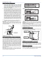
It is recommended that the appliance is installed in a location where the
space temperature is 32 °F (0°C) or higher. If the appliance is installed
in a location where the ambient temperature is below 32 °F (0°C), the
combustion byproducts could condense causing damage to the appli-
ance heat exchanger.
IMPORTANT:
The “VENT SYSTEM” must be installed as specified in
these instructions for Residential and Modular Homes.
This appliance may be common vented with another gas appliance for
residential installations as allowed by the codes and standards listed in
these instructions.
Approved Modular Homes must be vented with an approved roof jack
and may not be common vented with other appliances.
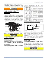
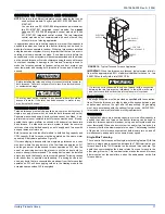
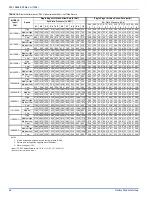
VENTING
Category I venting consists of vertically venting one or more appliances
in B-vent or masonry chimney (as allowed), using single wall metal pipe
or B-vent connectors. Type B-vent system extends in a general vertical
direction and does not contain offsets exceeding 45 degrees. A vent
system having not more than one 60 degree offset is permitted.
If installing furnace at altitudes between 2000 - 4500 ft. (610 – 1372 m),
vent pipe length must be reduced by 10 ft. (3.05 m). If the installation
requires the maximum allowable vent pipe length, the furnace must be
converted for high altitude operation. Refer to SECTION IV “GAS PIP-
ING” of these instructions and the proper high altitude application
instruction for details.
VENTING INTO AN EXISTING CHIMNEY
For Category I installations, the furnace shall be connected to a factory
built chimney or vent complying with a recognized standard, or a
masonry or concrete chimney lined with a material acceptable to the
authority having jurisdiction. Venting into an unlined masonry chimney
or concrete chimney is prohibited.
Whenever possible, B-1 metal pipe should be used for venting. Where
use of an existing chimney is unavoidable, the following rules must be
followed:
1.
The masonry chimney must be built and installed in accordance
with nationally recognized building codes or standards and must
be lined with approved fire clay tile flue liners or other approved
liner material that will resist corrosion, softening, or cracking from
flue gases.
THIS FURNACE IS NOT TO BE VENTED INTO AN
UNLINED MASONRY CHIMNEY.
2.
This furnace must be vented into a fire clay tile lined masonry
chimney only if a source of dilution air is provided, such as by com-
mon venting with a draft hood equipped water heater. If no source
of dilution air is available, Type B vent must be used, or masonry
chimney vent kit 1CK0603 or 1CK0604 must be used. Refer to the
instructions with the kit to properly apply these masonry chimney
kits.
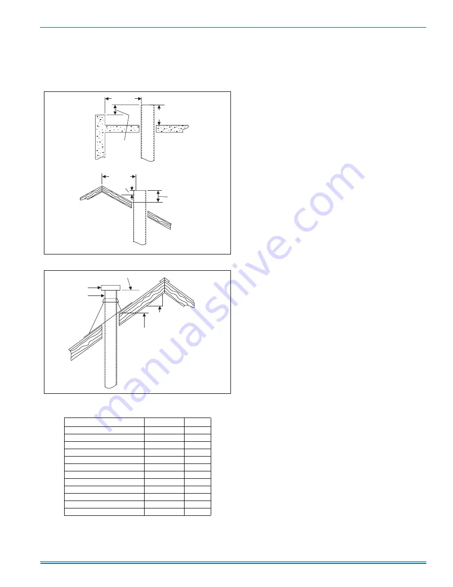
3.
The chimney must extend at least 3 ft (0.91 m) above the highest
point where it passes through a roof of a building and at least two
feet higher than any portion of the building with a horizontal dis-
tance of ten feet.
4.
The chimney must extend at least 5 ft (1.5 m) above the highest
equipment draft hood or flue collar.
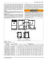
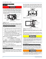
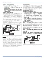
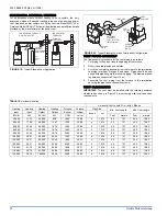
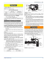
FIGURE 17:
Vent Termination
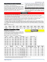
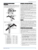
FIGURE 18:
Vent Termination
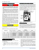
TABLE 9:
Roof Pitch
ROOF PITCH
H(min) ft
m
Flat to 6/12
1.0
0.30
6/12 to 7/12
1.25
0.38
Over 7/12 to 8/12
1.5
0.46
Over 8/12 to 9/12
2.0
0.61
Over 9/12 to 10/12
2.5
0.76
Over 10/12 to 11/12
3.25
0.99
Over 11/12 to 12/12
4.0
1.22
Over 12/12 to 14/12
5.0
1.52
Over 14/12 to 16/12
6.0
1.83
Over 16/12 to 18/12
7.0
2.13
Over 18/12 to 20/12
7.5
2.27
Over 20/12 to 21/12
8.0
2.44
WALL OR
PARAPET
CHIMNEY
NOTE: NO
HEIGHT ABOVE
PARAPET REQUIRED
WHEN DISTANCE
FROM WALLS OR
PARAPET IS MORE
THAN 10 FT (3.0 m).
3 FT (0.9 m)
MIN.
MORE THAN
10 FT (3.0 M)
2 FT(0.6 m)
MIN
RIDGE
CHIMNEY
HEIGHT ABOVE ANY
ROOF SURFACE WITHIN
10 FT (3.0 m) HORIZONTALLY
3 FT (0.9 m)
MIN
MORE THAN
10 FT (3.0 M)
LOWEST DISCHARGE OPENING
LISTED CAP
LISTED GAS
VENT
H (min) - MINIMUM HEIGHT FROM ROOF
TO LOWEST DISCHARGE OPENING
12
X
ROOF PITCH
IS X/12


