


035-19656-003 Rev. A (1004)
Unitary Products Group
15
†
A vent shall not terminate directly above a sidewalk or paved driveway that is located between two single family dwellings and serves both dwellings.
‡
Permitted only if veranda, porch, deck, or balcony is fully open on a minimum of two sides beneath the floor. For clearance not specified in ANSI Z223.1 / NFPA 54 or CSA B149.1-00.
Clearance in accordance with local installation codes and the requirements of the gas supplier and the manufacturer’s Installation Manual.
Any fresh air or make up inlet for dryer or furnace area is considered to be forced air inlet.
Avoid areas where condensate drippage may cause problems such as above planters, patios, or adjacent to windows where steam may cause fogging.
A terminus of a vent shall be either:
Fitted with a cap in accordance with the vent manufacturer’s installation instructions, or In accordance with the installation instructions for a special venting system.
* Does not apply to multiple installations of this furnace model. Refer to "VENTING MULTIPLE UNITS" in this section of these instructions.
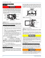
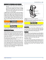
IMPORTANT: Consideration must be given for degradation of building materials by flue gases. Sidewall termination may require sealing or shielding of building surfaces with a corrosion resistant
material to protect against combustion product corrosion. Consideration must be given to wind direction in order to prevent flue products and/or condensate from being blown against
the building surfaces. If a metal shield is used it must be a stainless steel material at a minimum dimension of 20 inches. It is recommended that a retaining type collar be used that is
attached to the building surface to prevent movement of the vent pipe.
Responsibility for the provision of proper adequate venting and air supply for application shall rest with the installer.
Vent shall extend high enough above building, or a neighboring obstruction, so that wind from any direction will not create a positive pressure in the vicinity of the vent.
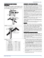
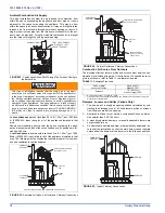
HORIZONTAL VENT APPLICATIONS AND
TERMINATION
When selecting the location for a horizontal combustion air / vent termi-
nation, the following should be considered:
1.
Observe all clearances listed in vent clearances in these instruc-
tions.
2.
Termination should be positioned where vent vapors will not dam-
age plants or shrubs or air conditioning equipment.
3.
Termination should be located where it will not be affected by wind
gusts, light snow, airborne leaves or allow recirculation of flue
gases.
4.
Termination should be located where it will not be damaged or
exposed to flying stones, balls, etc.
5.
Termination should be positioned where vent vapors are not objec-
tionable.
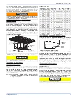
6.
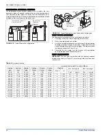
Horizontal portions of the vent system must slope upwards and be
supported to prevent sagging. The vent system may be supported
by the use of clamps or hangers secured to a permanent part of
the structure every 4 ft. (1.22 m).
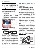
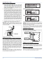
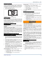
FAN-ASSISTED COMBUSTION SYSTEM
An appliance equipped with an integral mechanical means to either
draw or force products of combustion through the combustion chamber
and/or heat exchanger.
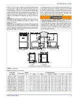
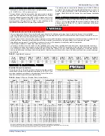
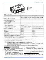
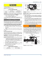
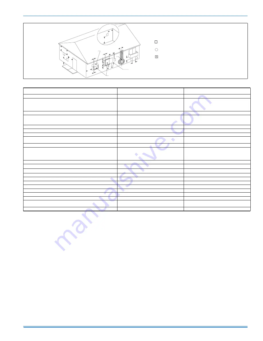
FIGURE 21:
Home Layout
L
E
D
B
V
V
V
X
V
B
V
J
X
B
B
B
V
V
F
V
C
B
X
V
I
V
G
H
A
M
K
OPERABLE
FIXED
CLOSED
VENT TERMINAL
AIR SUPPLY
AREA WHERE TERMINAL IS NOT PERMITTED
FIXED
CLOSED
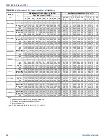
Canadian Installations
1
US Installation
2
A. Clearance above grade, veranda, porch, deck, or balcony
12 inches (30 cm)
12 inches (30 cm)
B. Clearance to window or door that may be opened
6 inches (15 cm) for applications
≤
10,000 Btuh (3kW),
12 inches (30 cm) for appliances > 10,000 Btuh (3kW)
and
≤
100,000 Btuh (30kW), 36 inches (91 cm)
for appliances > 100,000 Btuh (30kW)
6 inches (15 cm) for applications
≤
10,000 Btuh (3kW),
9 inches (23 cm) for appliances > 10,000 Btuh (3kW)
and
≤
50,000 Btuh (15kW), 12 inches (30 cm)
for appliances > 50,000 Btuh (30kW)
C. Clearance to permanently closed window
“
“
D. Vertical clearance to ventilated soffit located
above the terminal within a horizontal distance
of 2 feet (61 cm) from the center line of the terminal
“
“
E. Clearance to unventilated soffit
“
“
F. Clearance to outside corner
“
“
G. Clearance to inside corner
“
“
H. Clearance to each side of center line extended
above meter/regulator assembly
3 feet (91 cm) within a height 15 feet (4.5 m) above the
meter/regulator assembly
“
I. Clearance to service regulator vent outlet
3 feet (91 cm)
“
J. Clearance to nonmechanical air supply inlet to building
or the combustion air inlet to any other appliance
6 inches (15 cm) for applications
≤
10,000 Btuh (3kW),
12 inches (30 cm) for appliances > 10,000 Btuh (3kW)
and
≤
100,000 Btuh (30kW), 36 inches (91 cm)
for appliances > 100,000 Btuh (30kW)
6 inches (15 cm) for applications
≤
10,000 Btuh (3kW),
9 inches (23 cm) for appliances > 10,000 Btuh (3kW)
and
≤
50,000 Btuh (15kW), 12 inches (30 cm)
for appliances > 50,000 Btuh (30kW)
K. Clearance to a mechanical supply inlet
6 feet (1.83 m)
3 feet (91 cm) above if within 10 feet (3 cm) horizontally
L. Clearance above paved sidewalk or paved driveway located on public property 7 feet (2.13 m)
†
“
M.Clearance under veranda, porch, deck, or balcony
12 inches (30 cm)
‡
“
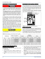
Dryer Vent
3 ft (91.44 cm)
3 ft (91.44 cm)
Plumbing Vent Stack
3 ft (91.44 cm)
3 ft (91.44 cm)
Gas Appliance Vent Terminal
3 ft (91.44 cm) *
3 ft (91.44 cm) *
Vent Termination from any Building Surface
12" (30.4 cm)
12" (30.4 cm)
Above Any Grade Level
12" (30.4 cm)
12" (30.4 cm)
Above anticipated snow depth
12" (30.4 cm)
12" (30.4 cm)
Any forced air inlet to the building.
10 ft (304.8 cm)
10 ft (304.8 cm)
The vent shall extend above the highest point where it passes through the roof,
not less than
18" (46 cm)
18" (46 cm)
Any obstruction within a horizontal distance
Not less than 18" (46 cm)
Not less than 18" (46 cm)
1.
In accordance with the current CSA B149.1-00, Natural Gas and Propane Installation Code.
2.
In accordance with the current ANSI Z223.1 / NFPA 54, National Gas Code.


