


035-19656-003 Rev. A (1004)
Unitary Products Group
17
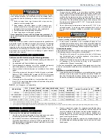
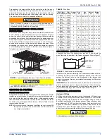
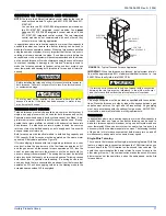
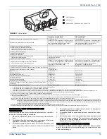
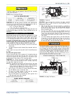
FIGURE 26:
Horizontal Air Inlet, Outlet and Chimney Connections
When a Category I furnace is removed or replaced, the original
venting system may no longer be correctly sized to properly vent
the attached appliances.
An improperly sized vent system can cause CARBON MONOXIDE
to spill into the living space causing personal injury, and or death.
FURNACE
W
A
TER
HEA
TER
OUTLET
AIR DUCT
INLET
AIR DUCT
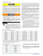
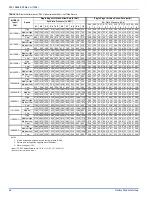
TABLE 12:
Free Area
BTUH Input
Rating
Minimum Free Area Required for Each Opening
Horizontal Duct
(2,000 BTUH)
Vertical Duct or
Opening to Outside
(4,000 BTUH)
Round Duct
(4,000 BTUH)
40,000
20 in
2
(129 cm
2
)
10 in
2
(64 cm
2
)
4” (10 cm)
60,000
30 in
2
(193 cm
2
)
15 in
2
(97 cm
2
)
5” (13 cm)
80,000
40 in
2
(258 cm
2
)
20 in
2
(129 cm
2
)
5” (13 cm)
100,000
50 in
2
(322 cm
2
)
25 in
2
(161 cm
2
)
6” (15 cm)
120,000
60 in
2
(387 cm
2
)
30 in
2
(193 cm
2
)
7” (18 cm)
130,000
65 in
2
(419 cm
2
)
33 in
2
(213 cm
2
)
7” (18 cm)
EXAMPLE: Determining Free Area.
Appliance 1Appliance
2Total
Input
100,000
+ 30,000 = (130,000
÷
4,000) = 32.5 Sq. In. Vertical
Appliance 1Appliance
2Total
Input
100,000
+ 30,000 = (130,000
÷
2,000) = 65 Sq. In. Horizontal
TABLE 13:
Unconfined Space Minimum Area in Square Inch
BTUH Input Rating
Minimum Free Area in Square Feet
Required for Each Opening
40,000
250 (23.23 m
2
)
60,000
375 (34.84 m
2
)
80,000
500 (46.45 m
2
)
100,000
625 (58.06 m
2
)
120,000
750 (69.68 m
2
)
130,000
813 (75.53 m
2
)
EXAMPLE: Square feet is based on 8 foot ceilings.
28,000 BTUH X 50 Cubic Ft. = 1,400 = 175 Sq. Ft.
1,000 8’ Ceiling Height
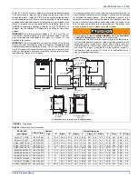
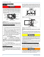
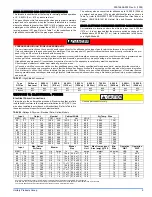
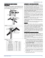
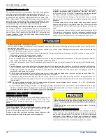
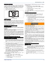
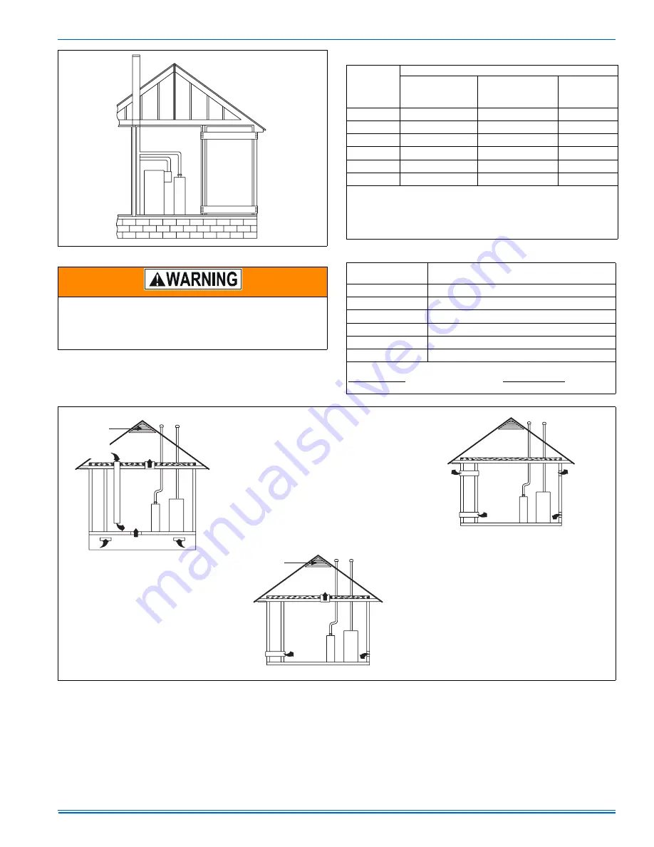
FIGURE 27:
Outside and Ambient Combustion Air
GABLE
VENT
GAS
VENT
SOFFIT
VENT
VENTILATED
ATTIC
TOP ABOVE
INSULATION
OPTIONAL
INLET (a)
OUTLET
AIR (a)
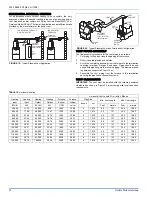
VENTILATED
CRAWL SPACE
GAS
WATER
HEATER
VENTILATED
ATTIC
TOP ABOVE
INSULATION
GAS
VENT
GABLE
VENT
SOFFIT
VENT
GAS
WATER
HEATER
INLET
AIR (a)
INLET
AIR (b)
GAS
VENT
OUTLET
AIR (a)
OUTLET
AIR (b)
INLET
AIR (a)
INLET
AIR (b)
GAS
WATER
HEATER
FURNACE
FURNACE
FURNACE
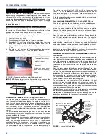
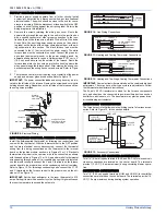
1.
An opening may be used in lieu of a duct to provide to provide the outside air
supply to an appliance unless otherwise permitted by the authority having
jurisdiction. The opening shall be located within 12” (30.5 cm) horizontally from,
the burner level of the appliance. Refer to “AIR SOURCE FROM OUTDOORS
AND VENT AND SUPPLY AIR SAFETY CHECK” in these instructions for
additional information and safety check procedure.
2.
The duct shall be either metal, or a material meeting the class 1
requirements of CAN4-S110 Standard for Air Ducts.
3.
The duct shall be least the same cross-sectional area as the free
area of the air supply inlet opening to which it connects.
4.
The duct shall terminate within 12 in (30.5 cm) above, and
within 24 in (61 cm) horizontally from, the burner level of
the appliance having the largest input.
5. A square or rectangular shaped duct shall only be used
when the required free area of the supply opening is
9 in (58.06 cm ) or larger. When a square or rectangular
duct is used, its small dimensionshall not be less than
3 in (7.6 cm).
2
2
6. An air inlet supply from outdoors shall be equipped with
a means to prevent the direct entry of rain and wind.
Such means shall not reduce the required free area of
the air supply opening.
7.
An air supply inlet opening from the outdoors shall
be located not less than 12” (30.5 cm) above the
outside grade level.
AIR SUPPLY OPENINGS AND DUCTS
COMBUSTION AIR SOURCE FROM OUTDOORS
1. Two permanent openings, one within 12 in (30.5 mm) of the top and
one within 12 in (30.5 mm) of bottom of the confined space,
shall communicate directly or by means of ducts
with the outdoors, crawl spaces or attic spaces.
Two
permanent openings,
2. One permanent openings, commencing within 12 in (30.5 mm)of the
top of the enclosure shall be permitted where the equipment has
clearances of at least 1 in (2.54 cm) from the sides and back and
6 in (15.24 cm) from the front of the appliance. The opening shall
communicate directly with the outdoors and shall have a minimum
free area of:
3. The duct shall be least the same cross-sectional area as the free
area of the air supply inlet opening to which it connects.
1 square in per 3000 Btu per hour (6.45 cm 0.879 kW) of the total
input rating of all equipment located in the enclosure.
2
a.
Not less than the sum of all vent connectors in the confined space.
b.
4. The blocking effects of louvers, grilles and screens must be given
consideration in calculating free area. If the free area of a specific
louver aor grille is not known.


