


035-19656-003 Rev. A (1004)
18
Unitary Products Group
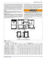
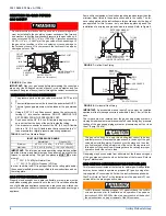
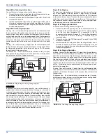
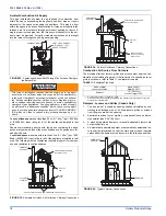
Ventilated Combustion Air
The ventilated attic space or a crawl space from which the combustion
air is taken must comply with the requirements specified in “AIR
SOURCE FROM OUTDOORS” in this instruction or in Section 5.3, Air
for Combustion and Ventilation of the National Fuel Gas Code, ANSI
Z223.1 (latest edition). This type installation requires two properly sized
pipes. One brings combustion air from a properly ventilated attic space
or crawl space and a second pipe that extends from the furnace vent
connection (top right of unit) to the exterior of the building.
Vent and Supply (Outside) Air Safety Check Procedure
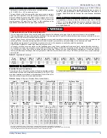
For Category I furnaces, vent installations shall be in accordance with
Parts 7 and 11 of the National Fuel Gas Code, ANSI Z223.1/NFPA 54,
and or Section 7 and Appendix B of the CSA B149.1, Natural Gas and
Propane Installation Codes, the local building codes, furnace and vent
manufacture's instructions.
Multi-story or common venting systems are permitted and must be
installed in accordance with the National Fuel Gas Code, ANSI Z223.1/
NFPA 54 and / or the CSA B149.1, Natural Gas and Propane Installa-
tion Codes, local codes, and the manufacture's instructions.
Vent connectors serving Category I furnaces shall not be connected
into any portion of mechanical draft systems operating under positive
pressure.
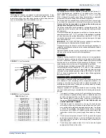
Horizontal portions of the venting system shall be supported to prevent
sagging using hangers or perforated straps and must slope upwards
not less than 1/4" per foot (0.635 cm/m) from the furnace to the vent ter-
minal.
It is recommended that you follow the venting safety procedure below.
This procedure is designed to detect an inadequate ventilation system
that can cause the appliances in the area to operate improperly causing
unsafe levels of Carbon Monoxide or an unsafe condition to occur.
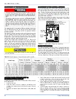
SECTION VIII: SAFETY CONTROLS
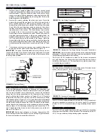
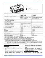
CONTROL CIRCUIT FUSE
A 3-amp fuse is provided on the control circuit board to protect the 24-
volt transformer from overload caused by control circuit wiring errors.
This is an ATO 3, automotive type fuse and is located on the control
board.
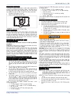
BLOWER DOOR SAFETY SWITCH
This unit is equipped with an electrical interlock switch mounted in the
blower compartment. This switch interrupts all power at the unit when
the panel covering the blower compartment is removed.
Electrical supply to this unit is dependent upon the panel that covers the
blower compartment being in place and properly positioned.
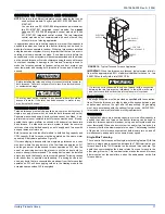
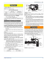
ROLLOUT SWITCH CONTROLS
These controls are mounted on the burner box assembly. If the temper-
ature in the burner box exceeds its set point, the ignition control and the
gas valve are de-energized. The operation of this control indicates a
malfunction in the combustion air blower, heat exchanger or a blocked
vent pipe connection. Corrective action is required. These are manual
reset controls that must be reset before operation can continue.
CARBON MONOXIDE POISONING HAZARD
Failure to follow the steps outlined below for each appliance connected to the venting system being placed into operation could result in carbon-
monxide poisoning or death.
The following steps shall be followed for each appliance connected to the venting system being placed into operation, while all other appliances
connected to the venting system are not in operation:
1. Inspect the venting system for proper size and horizontal pitch. Determine that there is no blockage, restriction, leakage, corrosion or other
deficiencies, which could cause an unsafe condition
2. Close all building doors and windows and all doors.
3. Turn on clothes dryers and TURN ON any exhaust fans, such as range hoods and bathroom exhausts, so they shall operate at maximum
speed. Open the fireplace dampers. Do not operate a summer exhaust fan.
4. Follow the lighting instructions. Place the appliance being inspected in operation. Adjust thermostat so the appliance shall operate contin-
uously.
5. Test each appliance (such as a water heater) equipped with a draft hood for spillage (down-draft or no draft) at the draft hood relief opening
after 5 minutes of main burner operation. Appliances that do not have draft hoods need to be checked at the vent pipe as close to the
appliance as possible. Use a combustion analyzer to check the CO2 and CO levels of each appliance. Use a draft gauge to check for a
downdraft or inadequate draft condition.
6. After it has been determined that each appliance properly vents when tested as outlined above, return doors, windows, exhaust fans, fire-
place dampers and any other gas burning appliance to their normal condition.
7. If improper venting is observed during any of the above tests, a problem exists with either the venting system or the appliance does not
have enough combustion air (Supply Air from outside) to complete combustion. This condition must be corrected before the appliance can
function safely.
NOTE:
An unsafe condition exists when the CO reading exceeds 40 ppm and the draft reading is not in excess of - 0.1 in. W.C. (-25 kPa) with
all of the appliance(s) operating at the same time.
8. Any corrections to the venting system and / or to the supply (outside) air system must be in accordance with the National Fuel Gas Code
Z223.1 or CAN/CGA B149.1-00 Natural Gas and Propane Installation Code (latest editions). If the vent system must be resized, follow the
appropriate tables in Appendix G of the above codes or for this appliance.
Main power to the unit must still be interrupted at the main power
disconnect switch before any service or repair work is to be done to
the unit. Do not rely upon the interlock switch as a main power dis-
connect.
Blower and burner must never be operated without the blower
panel in place.


