

035-19656-003 Rev. A (1004)
2
Unitary Products Group
SPECIFIC SAFETY RULES AND PRECAUTIONS
1.
Only Natural gas or Propane (LP) gas are approved for use with
this furnace.
2.
Install this furnace only in a location and position as specified in
SECTION I of these instructions.
3.
A gas-fired furnace for installation in a residential garage must be
installed as specified in SECTION I of these instructions.
4.
Provide adequate combustion and ventilation air to the furnace
space as specified in SECTION VII of these instructions.
5.
Combustion products must be discharged outdoors. Connect this
furnace to an approved vent system only, as specified in SEC-
TION VII of these instructions.
6.
Test for gas leaks as specified in SECTION XI of these instruc-
tions.
7.
Always install the furnace to operate within the furnace’s intended
temperature-rise range. Only connect the furnace to a duct system
which has an external static pressure within the allowable range,
as specified on the furnace rating plate.
8.
When a furnace is installed so that supply ducts carry air circulated
by the furnace to areas outside the space containing the furnace,
the return air shall also be handled by duct(s) sealed to the fur-
nace casing and terminating outside the space containing the fur-
nace.
9.
The furnace is not to be used for temporary heating of buildings or
structures under construction.
10. When installed in a Approved Modular Home or building con-
structed on-site, combustion air shall not be supplied from occu-
pied spaces.
11.
The size of the unit should be based on an acceptable heat loss
calculation for the structure. ACCA, Manual J or other approved
methods may be used.
SAFETY REQUIREMENTS
•
This furnace should be installed in accordance with all national
and local building/safety codes and requirements, local plumbing
or wastewater codes, and other applicable codes. In the absence
of local codes, install in accordance with the National Fuel Gas
Code ANSI Z223.1/NFPA 54, National Fuel Gas Code, and/or
CAN/CGA B149.1 Natural Gas and Propane Installation Code
(latest editions). Furnaces have been certified to the latest edition
of standard ANSI Z21-47 • CSA 2.3.
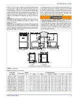
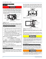
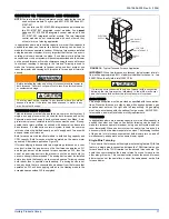
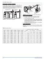
•
Refer to the unit rating plate for the furnace model number, and
then see the dimensions page of this instruction for return air ple-
num dimensions in Figure 1. The plenum must be installed
according to the instructions.
•
Provide clearances from combustible materials as listed under
Clearances to Combustibles.
•
Provide clearances for servicing ensuring that service access is
allowed for both the burners and blower.
•
These models
ARE NOT
CSA listed or approved for installation
into a
Manufactured (Mobile) Home
.
•
This furnace is not approved for installation in trailers or recre-
ational vehicles.
•
Failure to carefully read and follow all instructions in this
manual can result in furnace malfunction, death, personal
injury and/or property damage.
•
Furnaces for installation on combustible flooring shall not be
installed directly on carpeting, tile or other combustible material
other than wood flooring.
•
Check the rating plate and power supply to be sure that the elec-
trical characteristics match. All models use nominal 115 VAC, 1
Phase, 60-Hertz power supply. DO NOT CONNECT THIS APPLI-
ANCE TO A 50 HZ POWER SUPPLY OR A VOLTAGE ABOVE
130 VOLTS.
•
Furnace shall be installed so the electrical components are pro-
tected from water.
•
Installing and servicing heating equipment can be hazardous due
to the electrical components and the gas fired components. Only
trained and qualified personnel should install, repair, or service
gas heating equipment. Untrained service personnel can perform
basic maintenance functions such as cleaning and replacing the
air filters. When working on heating equipment, observe precau-
tions in the manuals and on the labels attached to the unit and
other safety precautions that may apply.
•
These instructions cover minimum requirements and conform to
existing national standards and safety codes. In some instances
these instructions exceed certain local codes and ordinances,
especially those who have not kept up with changing residential
and modular home construction practices. These instructions are
required as a minimum for a safe installation.
COMBUSTION AIR QUALITY
(LIST OF CONTAMINANTS)
The furnace will require
OUTDOOR AIR
for combustion when the fur-
nace is located in any of the following environments.
•
Restricted Environments
•
Commercial buildings
•
Buildings with indoor pools
•
Furnaces installed in laundry rooms
•
Furnaces installed in hobby or craft rooms
•
Furnaces installed near chemical storage areas
•
Chemical Exposure
The furnace will require
OUTDOOR AIR
for combustion when the fur-
nace is located in an area where the furnace is being exposed to the fol-
lowing substances and / or chemicals.
•
Permanent wave solutions
•
Chlorinated waxes and cleaners
•
Chlorine based swimming pool chemicals
•
Water softening chemicals
•
De-icing salts or chemicals
•
Carbon tetrachloride
•
Halogen type refrigerants
•
Cleaning solvents (such as perchloroethylene)
•
Printing inks, paint removers, varnishes, etc.
•
Hydrochloric acid
•
Cements and glues
•
Antistatic fabric softeners for clothes dryers
•
Masonry acid washing materials
When outdoor air is used for combustion, the combustion air intake duct
system termination must be located external to the building and in an
area where there will be no exposure to the substances listed above.
FIRE OR EXPLOSION HAZARD
Failure to follow the safety warnings exactly could result in serious
injury, death or property damage.
Never test for gas leaks with an open flame. Use a commercially
available soap solution made specifically for detection of leaks to
check all connections. A fire or explosion may result causing prop-
erty damage, personal injury or loss of life.


