background image

035-19656-003 Rev. A (1004)

24

Unitary Products Group

NOTES

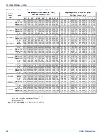
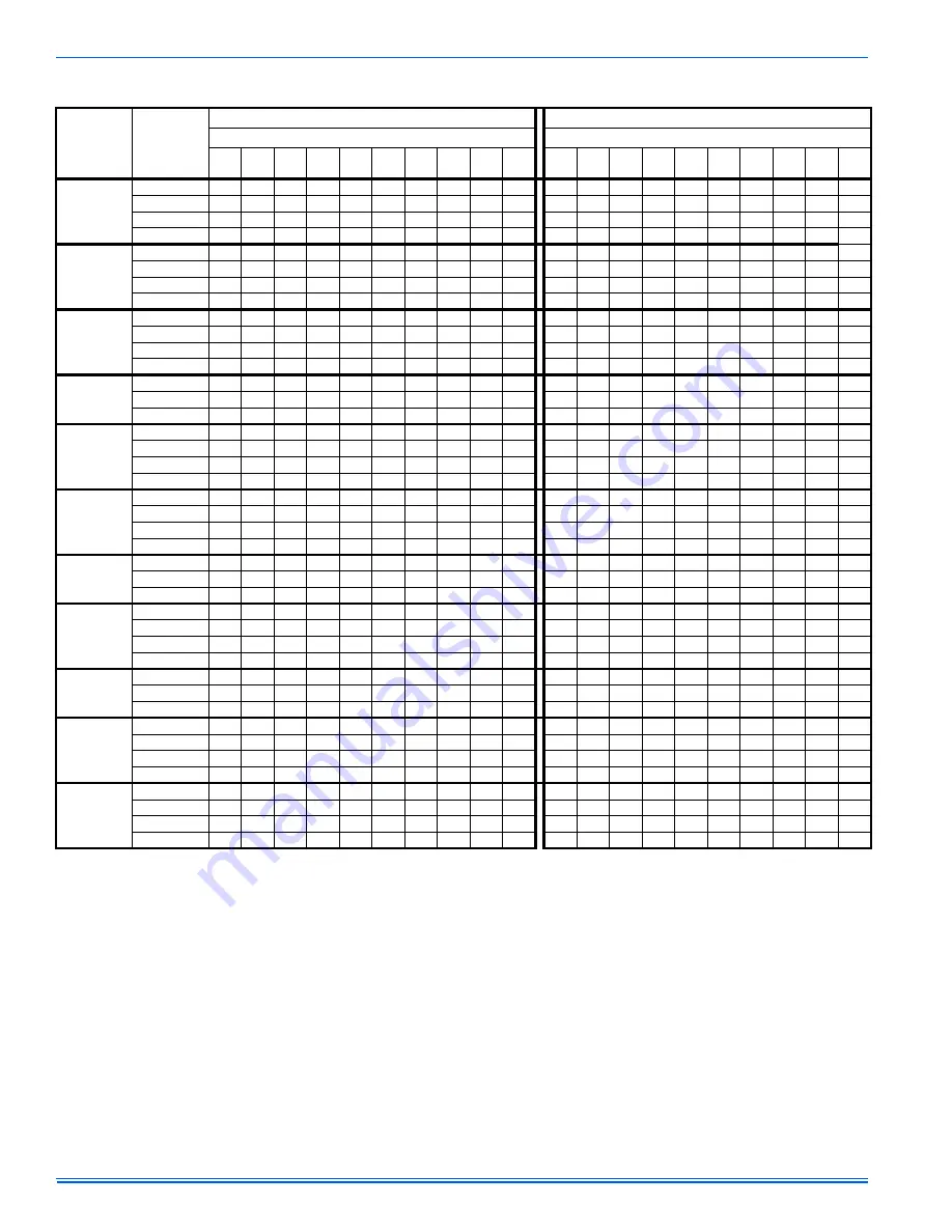
1. Airflow expressed in standard cubic feet per minute (CFM).

2. Return air is through side opposite motor (left side).

3. Motor voltage at 115 V.

* Input / CFM / Cabinet Width (A=14-1/2, B=17-1/2, C=21, D=24-1/2)

† Indicates model available in LoNOx.

TABLE 18: 

Blower Performance CFM - Upflow (without filter) - Left Side Return

MODELS

Input /

CFM

Speed 

Single Stage Left Side Airflow Data (SCFM)

Single Stage Left Side Airflow Data

 (cm/m)

Ext. Static Pressure (in. H2O) 

Ext. Static Pressure (kPa) 

0.1 0.2 0.3 0.4 0.5 0.6 0.7 0.8 0.9 1.0 

0.02

0.05

0.07

0.10

0.12

0.14

0.17

0.19

0.22

0.24

40/1200/A 

High 

1810 1730 1660 1570 1480 1390 1300 1200 1090 930  51.3 49.0 47.0 44.5 41.9 39.4 36.8 34.0 30.9 26.3 

Medium 

High 1390 1390 1350 1320 1270 1210 1150 1080 970  790  39.4 39.4 38.2 37.4 36.0 34.3 32.6 30.6 27.5 22.4 

Medium 

Low 1120 1120 1120 1110 1080 1080 1020 930  830  690  31.7 31.7 31.7 31.4 30.6 30.6 28.9 26.3 23.5 19.5 

Low 

880 910 920 920 910 870 820 740 650 510  24.9 25.8 26.1 26.1 25.8 24.6 23.2 21.0 18.4 14.4 

60/1200/A 

High 

1770 1690 1630 1560 1490 1390 1290 1190 1050 920  50.1 47.9 46.2 44.2 42.2 39.4 36.5 33.7 29.7 26.1 

Medium 

High 1400 1380 1350 1320 1280 1230 1160 1060 930  780  39.6 39.1 38.2 37.4 36.2 34.8 32.8 30.0 26.3 22.1 

Medium 

Low 1120 1130 1150 1130 1120 1080 1000 950  790  630  31.7 32.0 32.6 32.0 31.7 30.6 28.3 26.9 22.4 17.8 

Low 

880 900 900 900 880 850 790 730 660 530  24.9 25.5 25.5 25.5 24.9 24.1 22.4 20.7 18.7 15.0 

80/1200/A 

High 

1790 1720 1670 1590 1530 1450 1350 1260 1140 1000  50.7 48.7 47.3 45.0 43.3 41.1 38.2 35.7 32.3 28.3 

Medium 

High 1420 1370 1350 1320 1280 1230 1170 1090 990  840  40.2 38.8 38.2 37.4 36.2 34.8 33.1 30.9 28.0 23.8 

Medium 

Low 1080 1120 1110 1100 1080 1040 1000 920  820  690  30.6 31.7 31.4 31.1 30.6 29.4 28.3 26.1 23.2 19.5 

Low 

N/A 900 900 890 870 850 800 730 670 560  N/A 25.5 25.5 25.2 24.6 24.1 22.7 20.7 19.0 15.9 

80/1600/B 

High 

2000 1960 1930 1900 1800 1760 1710 1640 1550 1460  56.6  55.5  54.7  53.8  51.0  49.8  48.4  46.4  43.9  41.3 

Medium  1440 1440 1430 1420 1400 1380 1340 1300 1220 1150  40.8 40.8 40.5 40.2 39.6 39.1 37.9 36.8 34.5 32.6 

Low 

1220 1230 1230 1230 1200 1190 1170 1160 1110 1050  34.5 34.8 34.8 34.8 34.0 33.7 33.1 32.8 31.4 29.7 

80/2200/C 

High 

2710 2640 2560 2480 2360 2260 2160 2010 1860 1650  76.7  74.8  72.5  70.2  66.8  64.0  61.2  56.9  52.7  46.7 

Medium 

High 2110 2110 2070 2030 1980 1910 1850 1710 1570 1300  59.7 59.7 58.6 57.5 56.1 54.1 52.4 48.4 44.5 36.8 

Medium 

Low 1690 1690 1650 1610 1540 1480 1410 1280 1170 1030  47.9 47.9 46.7 45.6 43.6 41.9 39.9 36.2 33.1 29.2 

Low 

1350 1330 1310 1290 1260 1220 1150 1050 970  860  38.2 37.7 37.1 36.5 35.7 34.5 32.6 29.7 27.5 24.4 

100/1200/B 

High 

1780 1710 1640 1560 1490 1390 1290 1180 1030 820  50.4 48.4 46.4 44.2 42.2 39.4 36.5 33.4 29.2 23.2 

Medium 

High 1430 1410 1370 1340 1280 1220 1140 1040 890  730  40.5 39.9 38.8 37.9 36.2 34.5 32.3 29.4 25.2 20.7 

Medium 

Low 1140 1170 1150 1120 1080 1040 970  890  760  630  32.3 33.1 32.6 31.7 30.6 29.4 27.5 25.2 21.5 17.8 

Low 

920 940 950 940 920 890 850 770 660 560  26.1 26.6 26.9 26.6 26.1 25.2 24.1 21.8 18.7 15.9 

100/1600/B 

High 

1950 1890 1840 1790 1730 1660 1570 1480 1390 1300  55.2  53.5  52.1  50.7  49.0  47.0  44.5  41.9  39.4  36.8 

Medium  1440 1420 1400 1390 1350 1320 1270 1210 1150 1060  40.8 40.2 39.6 39.4 38.2 37.4 36.0 34.3 32.6 30.0 

Low 

1230 1210 1190 1180 1150 1130 1090 1050 990  920  34.8 34.3 33.7 33.4 32.6 32.0 30.9 29.7 28.0 26.1 

100/2000/C 

High 

2770 2670 2610 2540 2450 2340 2210 2070 1890 1730  78.4  75.6  73.9  71.9  69.4  66.3  62.6  58.6  53.5  49.0 

Medium High  2120 2060 2030 2000 1950 1880 1810 1720 1580 1370  60.0  58.3  57.5  56.6  55.2  53.2  51.3  48.7  44.7  38.8 

Medium Low  1690 1660 1630 1610 1560 1490 1420 1350 1240 1070  47.9  47.0  46.2  45.6  44.2  42.2  40.2  38.2  35.1  30.3 

Low 

1390 1370 1330 1290 1250 1200 1120 1010 910  850  39.4 38.8 37.7 36.5 35.4 34.0 31.7 28.6 25.8 24.1 

115/1600/C 

High 

2160 2070 1990 1900 1800 1690 1580 1430 1260 1000  61.2  58.6  56.4  53.8  51.0  47.9  44.7  40.5  35.7  28.3 

Medium  1760 1720 1690 1630 1560 1480 1390 1250 1080 890  49.8 48.7 47.9 46.2 44.2 41.9 39.4 35.4 30.6 25.2 

Low 

1510 1490 1470 1440 1380 1300 1210 1110 950  780  42.8 42.2 41.6 40.8 39.1 36.8 34.3 31.4 26.9 22.1 

115/2000/C 

High 

2740 2650 2560 2480 2380 2280 2170 1990 1840 1650  77.6  75.0  72.5  70.2  67.4  64.6  61.4  56.4  52.1  46.7 

Medium High  2120 2090 2040 2000 1940 1870 1780 1680 1550 1370  60.0  59.2  57.8  56.6  54.9  53.0  50.4  47.6  43.9  38.8 

Medium 

Low 1690 1670 1650 1610 1560 1510 1440 1310 1160 1030  47.9 47.3 46.7 45.6 44.2 42.8 40.8 37.1 32.8 29.2 

Low 

1390 1360 1330 1300 1250 1190 1100 1020 940  840  39.4 38.5 37.7 36.8 35.4 33.7 31.1 28.9 26.6 23.8 

130/2000/D 

High 

2680 2600 2520 2410 2300 2180 2050 1910 1730 1550  75.9  73.6  71.4  68.2  65.1  61.7  58.0  54.1  49.0  43.9 

Medium 

High 2140 2110 2070 1990 1930 1850 1770 1670 1530 1370  60.6 59.7 58.6 56.4 54.7 52.4 50.1 47.3 43.3 38.8 

Medium Low  1660 1640 1620 1570 1530 1470 1400 1310 1220 1090  47.0  46.4  45.9  44.5  43.3  41.6  39.6  37.1  34.5  30.9 

Low 

1370 1350 1320 1290 1240 1190 1140 1040 930  860  38.8 38.2 37.4 36.5 35.1 33.7 32.3 29.4 26.3 24.4 

Summary of Contents for PS8

Page 1: ...AL POWER 9 TWINNING AND STAGING 11 VENT SYSTEM 13 SAFETY CONTROLS 18 START UP AND ADJUSTMENTS 19 WIRING DIAGRAM 26 LIST OF FIGURES Dimensions 5 Furnace Base Rectangular Perforated Panel 6 Typical Atti...

Page 2: ...all instructions in this manual can result in furnace malfunction death personal injury and or property damage Furnaces for installation on combustible flooring shall not be installed directly on carp...

Page 3: ...e over clear ances for combustible materials where accessibility clearances are greater Installation in a residential garage 1 A gas fired furnace for installation in a residential garage must be inst...

Page 4: ...he total square inch of duct attached to the furnace plenum is 300 8 square inch This exceeds the recommended 280 square inch of duct In this example the duct system attached to the plenum has a suffi...

Page 5: ...above the maximum supply air temperature will cause the heat exchanger to overheat causing premature heat exchanger failure Improper duct sizing dirty air filters incorrect manifold pressure incorrect...

Page 6: ...thout a Cooling Coil Cabinet When installing this appliance the furnace must be installed so as to create a closed duct system the supply duct system must be con nected to the furnace outlet and the s...

Page 7: ...the filter exter nal to the cabinet IMPORTANT Some accessories such as electronic air cleaners and pleated media may require a larger side opening Follow the instruc tions supplied with that accessory...

Page 8: ...ge to the furnace or some of its components that will result in property damage and loss of life FIGURE 6 Gas Valve INLET WRENCH BOSS INLET PRESSURE PORT O N O FF ON OFF SWITCH Shown in ON position MA...

Page 9: ...conversions are required in order for the appliance to satisfactory meet the application An authorized distributor or dealer must make all gas conversions In Canada a certified conversion station or o...

Page 10: ...Figures 13 or 14 Apply strain relief to thermostat wires passing through cabinet If air conditioning equipment is installed use thermostat wiring to connect the Y and C terminals on the furnace contr...

Page 11: ...e mixing device must be installed before any ducts that supply air to occupied spaces Twinning causes both indoor fans to operate simultaneously If a mixing device is not used any ducts that are conne...

Page 12: ...Staging The single wire twinning feature of this board can also be used for stag ing of two furnaces With this feature a single wire is connected between the TWIN terminal on one furnace board to the...

Page 13: ...ted for high altitude operation Refer to SECTION IV GAS PIP ING of these instructions and the proper high altitude application instruction for details VENTING INTO AN EXISTING CHIMNEY For Category I i...

Page 14: ...FAN ASSISTED FURNACE WATER HEATER FAN ASSISTED FURNACES VENT PIPE HOT WATER TANK FURNACE OPTIONAL SIDEWALL VENT SYSTEM field supplied EXTERIOR VENT HOOD FIGURE 20 Typical Sidewall Vent and Terminatio...

Page 15: ...ent sagging The vent system may be supported by the use of clamps or hangers secured to a permanent part of the structure every 4 ft 1 22 m FAN ASSISTED COMBUSTION SYSTEM An appliance equipped with an...

Page 16: ...sub tracting the blockage area of all fixed louvers grilles or screens from the gross area of the opening 2 Apertures in a fixed louver a grille or screen shall have no dimen sion smaller than 0 25 0...

Page 17: ...horizontally from the burner level of the appliance Refer to AIR SOURCE FROM OUTDOORS AND VENT AND SUPPLY AIR SAFETY CHECK in these instructions for additional information and safety check procedure 2...

Page 18: ...he combustion air blower heat exchanger or a blocked vent pipe connection Corrective action is required These are manual reset controls that must be reset before operation can continue CARBON MONOXIDE...

Page 19: ...ngth x 1 8 0 3 cm diameter tubing 1 5 16 0 8 cm tee 1 5 16 0 8 cm x 1 8 3 175 mm reducing coupling 1 1 8 0 3 cm adapter There is a accessory kit 1PK0602 available from Source 1 which has the following...

Page 20: ...divided by the time it took to measure 2 cubic ft 0 0566 m3 of gas from the gas meter For Propane LP Gas multiply the Heat content of the gas MJ m3 or Default 93 14 times 0 00283 m3 of gas measured a...

Page 21: ...e the unit back in operation 3 Adjust manifold pressure by adjusting gas valve regulator screw for the appropriate gas per the following IMPORTANT If gas valve regulator is turned in clockwise manifol...

Page 22: ...turn opening size in square inches to determine the proper filter pres sure drop 3 Determine the External System Static Pressure ESP without the filter 4 Select a filter pressure drop from the table b...

Page 23: ...7 Medium 1470 1450 1440 1430 1390 1360 1310 1270 1220 1150 41 6 41 1 40 8 40 5 39 4 38 5 37 1 36 0 34 5 32 6 Low 1260 1260 1260 1260 1250 1200 1150 1110 1070 1010 35 7 35 7 35 7 35 7 35 4 34 0 32 6 31...

Page 24: ...52 4 48 4 44 5 36 8 Medium Low 1690 1690 1650 1610 1540 1480 1410 1280 1170 1030 47 9 47 9 46 7 45 6 43 6 41 9 39 9 36 2 33 1 29 2 Low 1350 1330 1310 1290 1260 1220 1150 1050 970 860 38 2 37 7 37 1 3...

Page 25: ...s SEE CHART PAGE 6 1PS0302 1PS0311 1PS0312 1BR0314 EXTERNAL BOTTOM RETURN FILTER with High Velocity Filter for Horizontal Application for Upflow Bottom Return Application 14 1 2 CABINETS 1BR0317 17 1...

Page 26: ...035 19656 003 Rev A 1004 26 Unitary Products Group SECTION X WIRING DIAGRAM FIGURE 32 Wiring Diagram...

Page 27: ...035 19656 003 Rev A 1004 Unitary Products Group 27 NOTES...

Page 28: ...e without notice Printed in U S A 035 19656 003 Rev A 1004 Copyright by York International Corp 2004 All rights reserved Supersedes 035 19656 002 Rev A 0704 Unitary 5005 Norman Product York OK Group D...

Reviews: