HF25D DC RESISTANCE WELDING SYSTEM
990-333
C-1
APPENDIX C
HF25 DC RESISTANCE WELDING
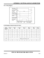
SYSTEM TIMING
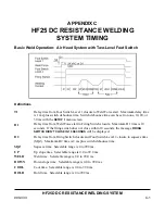
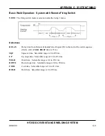
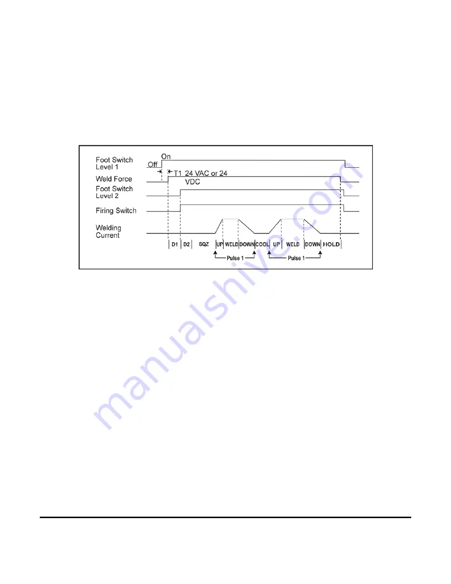
Basic Weld Operation: Air Head System with Two-Level Foot Switch
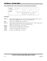
Definitions
T1
Delay time from Foot Switch Level 1 closure to Weld Force start. Maximum delay time
is 1 ms plus switch debounce time. Switch debounce time can be set to none, 10, 20, or
30 ms with the
SETUP 1
menu screen.
D1
Delay time from Weld Force start to Firing Switch closure. Maximum D1 time is 10
seconds. If the firing switch does not close within 10 seconds, the message
FIRING
SWITCH DIDN’T CLOSE IN 10 SECONDS
will be displayed.
D2
Delay time from Firing Switch closure and Foot Switch Level 2 closure to squeeze time
(SQZ). Maximum D2 time is 2 ms plus switch debounce time.
SQZ
Squeeze time. Selectable range is 0 to 999 ms.
UP
Up slope time. Selectable range is 0.0 to 99.0 ms.
WELD
Weld time. Selectable range is 0.0 to 99.0 ms.
DOWN
Down slope time. Selectable range is 0.0 to 99.0 ms.
COOL
Cool time: Selectable range is 0.0 to 99.0 ms.
HOLD
Hold time. Selectable range is 0 to 999 ms.
Summary of Contents for HF25A
Page 9: ...HF25D DC RESISTANCE WELDING SYSTEM 990 333 ix ...
Page 10: ......
Page 20: ......
Page 84: ...CHAPTER 6 CALIBRATION HF25D DC RESISTANCE WELDING SYSTEM 990 333 6 4 Final Calibration Setup ...
Page 113: ......
Page 129: ......
Page 153: ......
Page 171: ......

