


HF25 DC RESISTANCE WELDING SYSTEM
990-333
D-1
APPENDIX D
LVDT OPTION
Section I. Description
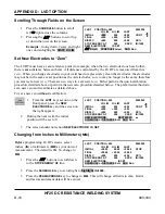
Overview
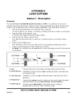
The optional
Linear Variable Differential Transformer
(
LVDT
) is a combination of an electro-
mechanical device attached to the weld head, which is electronically linked to software installed in the
Control. This combination will be referred to simply as
the LVDT
. This option allows the user to:
•
Measure initial part thickness as the electrodes close on the part.
(If too thin, parts may be missing. If too thick, something extra may be in the way of the parts.)
•
Measure displacement during the weld.
(To measure the collapse of the parts during welding.)
•
Measure final part thickness after the weld.
(Too thick maybe an indication of a cold weld. Too thin maybe an over-welded or blown
weld.)
•
Weld to a preset displacement.
(The weld energy will stop when the parts reach a user-programmed displacement value.)
•
Actuate a relay when specific LVDT conditions are reached.
(
Example
: If a weld has too much displacement, a relay could trigger an alarm for the operator
or automation.)
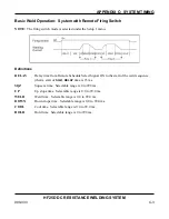
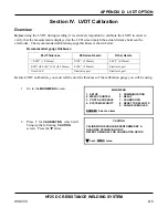
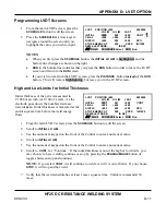
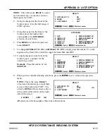
1 = Zero
The point where the two electrodes touch (
zero
distance between them).
2 = Initial Thickness
The thickness of the weld pieces
before
welding takes place (measured at the
end of squeeze time).
3 = Final Thickness
The thickness of the weld
after
welding takes place (measured at the end of
hold time).
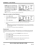
4 = Displacement
The amount of
collapse
when the weld pieces were forced together during the
weld (the difference between
Initial Thickness
and
Final Thickness
).
5 = Stop Energy At
Also referred to as
WELD STOP
.
The thickness of the weld pieces
(programmed by the user) at which weld energy stops.
Summary of Contents for HF25A
Page 9: ...HF25D DC RESISTANCE WELDING SYSTEM 990 333 ix ...
Page 10: ......
Page 20: ......
Page 84: ...CHAPTER 6 CALIBRATION HF25D DC RESISTANCE WELDING SYSTEM 990 333 6 4 Final Calibration Setup ...
Page 113: ......
Page 129: ......
Page 153: ......
Page 171: ......


