APPENDIX D: LVDT OPTION
HF25 DC RESISTANCE WELDING SYSTEM
D-4
990-333
Section III. Before You Start
•
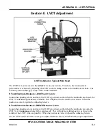
Check the connections from the LVDT on the weld head to the Control.
•
Verify that the LVDT moves freely with the electrodes.
•
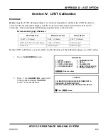
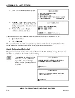
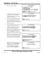
Calibrate the LVDT following the procedures in
Section IV, LVDT Calibration
.
•
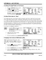
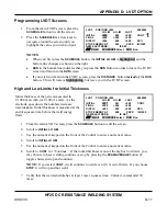
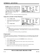
To fully utilize the benefits of the LVDT, you should perform several welds
before
you
program high or low limits for Initial Thickness, Final Thickness, or Displacement.
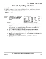
Look to see what your results are in the
LAST
(Last Weld) column. You need to know
what your typcial initial thickeness, typical final thickness is, typical displacement is so
you have a reference point.
•
Run through this processs development as you would any other process so you can
reasonably predict what is going to happen.
After
you have developed the process, then
you can put limits around each value in order to catch changes in the process.
Summary of Contents for HF25A
Page 9: ...HF25D DC RESISTANCE WELDING SYSTEM 990 333 ix ...
Page 10: ......
Page 20: ......
Page 84: ...CHAPTER 6 CALIBRATION HF25D DC RESISTANCE WELDING SYSTEM 990 333 6 4 Final Calibration Setup ...
Page 113: ......
Page 129: ......
Page 153: ......
Page 171: ......

