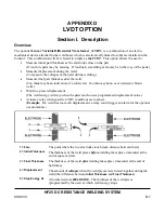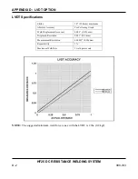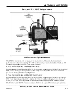
APPENDIX D: LVDT OPTION
HF25 DC RESISTANCE WELDING SYSTEM
D-6
990-333
3
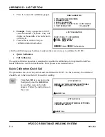
Press
6
to input the calibration gauges.
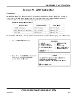
PRE-CALIBRATION
1. TEST HF25 (T-232 REQUIRED)
2. CALIBRATE HF25
3. RESET CALIBRATION
4. SET CURRENT SHUNT VALUE 6. LVDT GAUGE
5. TEST SERIAL PORT
7. CALIB LVDT
4
Example
: Using a gauge that is 0.100”,
enter the numbers
1
,
0
, and
0
. They will
display as thousandths of an inch shown
on the right.
5
Press menu to return to the pre-
calibration menu shown above.
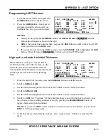
LVDT CALIBRATION
THICK > THIN + 17.6 INCHES/1000
V
THIN 000.0 IN/1000
W
THICK 100.0 IN/1000
NUMBER Select, MENU Previous menu
After the calibration gauge thickness is entered, there are two ways to calibrate the LVDT:
•
Quick Calibration
•
Full Calibration
The quick calibration procedure is designed to expedite the calibration of air operated Unitek Peco
heads. Otherwise, use the full calibration. Both processes are detailed below:
Quick Calibration (Quick Cal)
The procedure sets a new zero position and recalibrates the LVDT. For best accuracy, the weldhead
should be set to the force that will be used for welding.
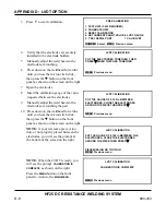
1
From the
LVDT
keys section on the
front panel, press the
QUICK CAL
key and the screen on the right
appears. Follow the instructions on
the screen
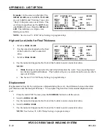
LVDT QUICK CAL
REMOVE ANY PIECE BETWEEN ELECTRODES.
PRESS
W
TO CONTINUE CALIBRATION.
V
ABORT CAL
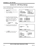
LVDT QUICK CAL
REMOVE ANY PIECE BETWEEN ELECTRODES.
PRESS FOOTSWITCH.
V
ABORT CAL
Summary of Contents for HF25A
Page 9: ...HF25D DC RESISTANCE WELDING SYSTEM 990 333 ix ...
Page 10: ......
Page 20: ......
Page 84: ...CHAPTER 6 CALIBRATION HF25D DC RESISTANCE WELDING SYSTEM 990 333 6 4 Final Calibration Setup ...
Page 113: ......
Page 129: ......
Page 153: ......
Page 171: ......

